Information about the manufacturer of the thickness planer SR-6-9
CP 6-9 thickness woodworking machine is the Stavropol Machine Tool Plant Krasny Metallist , which has specialized in the production of woodworking machines since 1932. The plant was founded in 1902 and is located in the city of Stavropol.
Machine tools produced by the Stavropol machine tool plant Krasny Metalist
- SR-6-6
Thicknessing machine, one-sided - SR-6-9
Thicknessing machine, one-sided - SR-6-10
Thicknessing machine, one-sided - SR-8-2
Single-sided thickness planer
SR 6-9 Thicknessing machine, one-sided. Purpose, scope
Thicknessing machine SR-6-9 belongs to a new series of thicknessing machines produced in the mid-eighties, namely: SR3-6 (300 mm), SR6-9 (600 mm), SR8-1 (800 mm).
Thicknesser single-sided machine SR-6-9 is designed for longitudinal, one-sided planing to a thickness of 5 to 200 mm of surfaces of flat workpieces up to 630 mm wide, made of coniferous and deciduous wood with a moisture content of no more than 15%. The SR-6-9 machine is a universal equipment and is used in serial and small-scale production of joinery products in the construction industry, furniture, shipbuilding, and carriage building.
Thicknessing machine SR-6-9 is used for flat planing (milling) of boards, beams or panels to size in thickness. It is used in enterprises and workshops for the production of joinery and construction products, laminated panels, furniture production, wooden housing construction and other woodworking industries.
Processing of workpieces is carried out by a 4-knife cylindrical shaft with wedge fastening of the knives in the shaft housing. A special clamp is installed in front of the knife shaft to support the wood fibers in the cutting area and eliminate chips on the surface being processed.
The table on which the workpieces are fed is of a cast rigid structure, equipped with support rollers to reduce friction when moving the material being processed.
The table is raised and lowered in height, depending on the thickness of the material being processed, mechanically using a separate electric motor or manually using a flywheel, followed by fixation to prevent spontaneous lowering of the table.
The bottom (base) surface of the workpiece must be processed on a jointer. The deviation of the base face of the workpiece should not exceed 0.15 mm over a length of 1000 mm.
The workpiece feed is mechanical. The feeder is driven by the engine through a gearbox.
The room where the machine is installed must meet the requirements of class P-IIa according to PUE-98.
Climatic design and machine placement category - UHL4.2, storage conditions category - 2 according to GOST 15150-69.
Distinctive features of the thickness planer CP 6-9:
- The machine has a cast frame, which significantly increases its rigidity;
- The table is raised and lowered in height mechanically using a separate electric motor or manually, followed by fixation to prevent spontaneous lowering of the table;
- The machine has three drive rollers, which significantly improves the traction capacity of the feed mechanism;
- The table is equipped with support rollers, including rear drive ones, to increase the reliability of feeding when moving the workpiece;
- The front feed roller is sectional, which allows simultaneous processing of several workpieces with a difference in thickness of up to 4 mm;
- Processing of workpieces is carried out using a 4-knife cylindrical shaft with wedge-shaped fastening of knives in the body;
- The machine is equipped with an automatic cutting shaft brake for safe operation;
- A special cast clamp is installed in front of the knife shaft to support wood fibers in the cutting area and eliminate chips on the surface being processed;
- Claw protection on the loading side, preventing reverse ejection of the workpiece during processing;
- Electrical locking, eliminating the possibility of turning on the machine when the fence is open.
What is a thicknesser, its functions and design
It is correctly called a “thicknessing machine”. We make markings or planing relative to one base. Makita 2012 nb. A review will be made and some of its features, pros and cons will be discussed.
Products for inventors Link to the store.
First, let's look at what a thickness planer is for, what can this tool do? This is necessary because to this day there are questions, for example, why do I need a jointer if I have a thickness planer. That is, people are sure that if we put some kind of board into this tool, then it doesn’t matter how crooked or even it is, the output we get is perfectly calibrated. This is a deep misconception, ignorance of the principle of operation of a thickness planer.
Let's consider the theoretical part and the school geometry course. These are tools for calibrating lumber by thickness. It does not level the workpiece, it can trim it slightly, but it cannot make a base. The only task is to plan the board and ensure the same thickness along the entire length and width.
DIY electronics in a Chinese store.
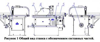
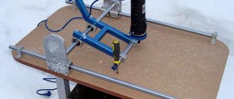
SR-6-9 General view of the thickness planer
Photo of thickness planer CP 6-9
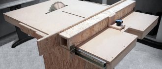
Photo of thickness planer CP 6-9
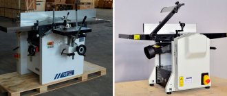
Photo of thickness planer CP 6-9
Location of components and controls for thickness planer SR-6-9
Location of the components of the machine CP 6-9. Rice. 3
Location of machine controls CP 6-9. Rice. 4
Location of machine controls CP 6-9. Rice. 5
Location of machine controls CP 6-9. Rice. 6
Location of components of thickness planer SR 6-9
- Bed - CP6-9.10.000 - Fig. 3, pos. 1
- Table - CP6-9.12.000 - Fig. 3, pos. 2
- Feed roller (front) - CP6-9.22.000 - Fig. 4, pos. 21, Fig. 10
- Clamps - CP6-9.24.000 - Fig. 4, pos. 20, Fig 9
- Knife shaft - CP6-9.25.000 - Fig. 4, pos. 19, Fig. 8
- Feed roller (rear) - CP6-9.28.000 - Fig. 4, pos. 22, Fig. eleven
- Feed drive - CP6-9.30.000 - Fig. 3, pos. 3, Fig 12
- Sound-absorbing curtain - CP6-9.78.000 - Fig. 13*
- Electrical equipment - CP6-9.80.000 - Fig. 3, pos. 62
Location of controls for thickness planer SR 6-9
- Load indicator
- Light indicator indicating the presence of voltage
- Knife shaft start button
- Up button for table movement
- Down button for table movement
- Feed start button
- Stop button general
- Stop button general
- Local lighting switch
- Input switch
- Handwheel for manual table movement
- Feed speed adjustment handwheel
- Mechanical table clamp handle
- Handle for moving table rollers
Kinematic diagram of thickness planer SR-6-9
Kinematic diagram of thickness planer SR 6-9
The kinematic chains of the machine carry out the following movements:
- Knife shaft rotation
- Rotation of feed rollers
- Mechanical and manual movement of the table up and down
- Manual feed speed setting
- Manual table clamp
The figure shows the kinematic diagram of a single-sided thickness planer CP 6-9. The knife shaft 35 is driven into rotation by the electric motor 1 through a V-belt transmission with pulleys 2 and 3. The shaft is braked by brake 36.
The feed mechanism is three-roller. The drive of the upper feed rollers 37 and 39 and the rear lower roller 42 is carried out from a two-speed electric motor 4, a coupling and a gearbox mounted on one plate. The gearbox contains two electromagnetic couplings 40 and 41, with the help of which gearbox stages with different gear ratios are activated.
When clutch 40 is turned on, rotation is applied to the rollers through gears 5-7, 9-10, 11-12, 13-14, 15-16 and a chain drive with sprockets 17-21. When clutch 41 is engaged, rotation is transmitted through gears 6-8, and then along the same kinematic chain.
The required feed speed is set using two switches (for couplings and motor) according to the setting table, where the corresponding switch position is indicated for each speed. Four feed speed values in the range of 8...24 m/min fully satisfy consumers, and simplification of the kinematic chain of the feed drive increases the reliability of the machine.
The machine table 38 has adjustable vertical movement along the guides. Rotation from the electric motor 34 through a belt drive 28-29, a worm gear 30, a chain drive 31-32, bevel gears 23-24 and 26-27 is supplied to two screw pairs 22 and 25. The table moves up and down only with continuous pressure on button. To prevent damage to the lifting mechanism, a safety clutch 33 is used. Manual movement of the table is carried out by a handwheel 43 through a gear clutch 44.
The table is fixed in a given position by manually turning the handle, which clamps the table guide through an eccentric and a rod.
The best planes
DEWALT DW735X Two Speed Planer
DEWALT DW735X Two Speed Planer
Starting with this piece of equipment, we present a high-performance and durable planing machine. The three-knife cutter head gives a very powerful result. It is also a 20,000 rpm engine. With a two-speed gearbox, users can change the feed speed to optimize cutting. The maximum cutting depth is 1/8" with a full capacity of 6" deep and 13" wide.
The downside to this plane comes in two forms: price and weight. It's on the higher end of the price spectrum, making it a serious investment. That's why it's ideal for the professional or intensive user. The three blades also have a short lifespan with high replacement costs. Some reviewers have chosen to purchase different knives to get better results, but that would be a separate purchase based on individual needs.
On the other hand, the DeWalt plane will also provide reliable customer service and a three-year warranty. Reviews of the planer highlight the customer service and quality of the equipment, with 75% of those surveyed giving it five stars. Most reviews indicate that it is worth the price tag.
DEWALT DW735X Pros
- 20,000 rpm
- Cutter head with three knives
- Two-speed gearbox
- Ideal for professionals
- 3 years warranty
DEWALT DW735X Cons
- Weight is not suitable for portability
- High price
- Replacement knives are expensive
DEWALT Jointer, 2 Speed, 13" (DW735X)
- Powerful 15 AMP, 20,000 RPM motor (10,000 RPM cutter head speed) easily handles large cuts in wider materials
- Three-knife cutting head extends knife life by 30 percent, fan pushes chips out of chip head and pulls them out of machine
- Two-speed gearbox allows users to change feed speed to optimize cuts per inch at 96 or 179 CPI
- Maximum cutting depth 1/8" x 6" deep x 13" wide
- Includes feeding and unloading tables and an additional set of knives. Reduce feed rate to 14 ft/min. Aircraft type: stationary
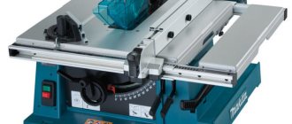
Makita 2012NB 12" machine
Makita 2012NB 12" machine
In contrast to the weight of the DeWalt DW735X is the Makita 2012 NB. This machine has a compact design, which enhances its portability. If the project needs transportation to different job sites, this is a good option. It also has a low noise level, making it more convenient and safe to use. For safety purposes, the machine is equipped with an LED light to indicate when it is connected to power and ready to use.
Don't let the size fool you - this is still a powerful piece of equipment. The Makita has an 8500 RPM motor and a maximum entry width of 12 inches. The cutting depth is 1/8 inch. The planning depth is 1/16 inch. Reviews indicate that it is easy to use, making it a suitable choice for new woodworking businesses. It has a one-year warranty. This purchase comes with dual planer blades, wrenches and a tool box.
Like the DeWalt DW735X, the downside is the price. However, there are several financing options available at some retailers. The dust collection hood is also sold separately, creating another purchase. Some reviews also report that replacing the blade can be difficult.
Makita 2012NB Pros
- Engine 8500 rpm
- Compact design suitable for transport
- Low noise level
- 1 year warranty
Makita 2012NB Cons
- Expensive
- Dust collection hood sold separately
DEWALT DW734 15 Amp 12-1/2" Tabletop Planer
DEWALT DW734 15 Amp 12-1/2" Tabletop Planer
Say hello to the powerful DeWalt DW734. This tabletop planer has 20,000 RPM and is capable of processing large, deep cuts in hardwood. It also has a 3-knife cutter head with disposable and reversible steel blades. The power of this planer is 96 cuts per inch, one of the best in portable planers.
In addition to its power, the price is also well suited to many budgets. This is an excellent alternative to more expensive models on the market. It is durable and designed to last for many projects. Most planer reviews show that it is a solid investment for woodworking businesses. It also comes with a 3-year warranty.
Of course, there are also disadvantages. Like the DW 735, this planer is best suited for benchtop use. It's heavy despite being considered portable. Standard blades wear out over time and require replacement. Some reviews indicated that the dust collection system left much to be desired.
DEWALT DW734 Pros
- 20,000 rpm
- Cutter head with three knives
- Price guide
- 3 years warranty
DEWALT DW734 Cons
- Weight is not suitable for portability
- Dust collection system
- Replacement knives are expensive
DEWALT Tabletop Planer, Single Speed, 15 Amp, 12-1/2-Inch (DW734)
- Three blade cutting head with 10,000 rpm rotation speed produces 96 cuts per inch, one of the best options for any portable plane
- Disposable, reversible knives increase knife life by 30 percent and allow for quick and easy knife replacement
- Four-column carriage lock dramatically reduces movement that causes sticking
- Extra long feed and exit tables provide 33-1/2 inches of material support
- Powerful 15.0A, 20,000RPM motor handles larger, deeper cuts in hardwood.
Delta Power Tools 22-555 Portable Thickness Planer
Rotary hammer Delta Power Tools 22-555
For smaller projects or more casual users, there is the Delta planer. This model has a small but powerful 15 amp motor, ideal for a small shop. The maximum cutting depth is 3/32”; The maximum feeding width is 13 inches. It has adjustable feed and discharge to reduce trimming and handle long pieces. Knives with double blade and disposable. It has a low price, which makes it very profitable. It is accurate and durable, with easy blade changes and low shot production. It also comes with a five-year limited warranty from a reputable brand: Delta has been in business for almost 90 years!
This part is suitable for the more casual user, as its lack of power is not suitable for professional or heavy users. It is not powerful enough to handle harder woods. Considering the price, warranty and intended use, this would be a safe purchase.
Power tool Delta 22-555 Pros
- 15 amp motor
- Double knives
- Low price
- Five-year warranty
- Good for the average user
Power tool Delta 22-555 cons
- Not powerful enough for professional or heavy user
- Not suitable for harder woods
Delta 22-555 13 power tool in portable planer
- Powerful 15A motor capable of handling the most difficult tasks
- Four-column design provides superior stability for smooth, precise gliding
- Quick-change knife system with disposable dual-blade knives allows knives to be changed without the need for complex centering devices
- Adjustable infeed and outfeed tables to better support long parts and reduce sniping
- The reversible dust collector allows you to collect chips from the right or left side of the planer. Machine Dimensions: 21-5/8 x 23-5/8 x 20-1/8 inches
WEN 6552 3-blade tabletop planer
WEN 6552 Tabletop Planer with 3 Blades and 15 Amp
Another option for the casual user or beginning woodworker is the WEN Model 6552. This 15-amp motor can handle flat boards up to 6 inches thick and 13 inches wide. The engine is capable of producing 25,500 cuts per minute. The three-blade design makes it easy to work with all types of wood—even hardwood. It also comes with a 2-year warranty and weighs 66 pounds: on the lighter side for planers. WEN products are also supported by a network of service technicians throughout the country.
The purchase also comes with a cast iron base, height-adjustable inlet/output tables, dust port with fan, and more. The auxiliary fan is great for removing shavings and sawdust from your work area. The combination of cast iron base and onboard planer creates a durable planer—no need to worry about wobbly operation. This model is also a great price, and reviewers indicate that quality doesn't sacrifice price.
The size and power of this planer are not suitable for professional use. The home or casual user will benefit greatly from this purchase.
WEN 6552 Pros
- Powerful 15 amp motor
- Capable of 25,500 contractions per minute
- Three-blade design
- Capable of processing various types of wood
- Price guide
- 2 years warranty
WEN 6552 Cons
- Size and power not suitable for professional use
WEN 6552 15 Amp 3-Blade Planer, 13"
- Built-in material removal sensor informs users of the cutting depth of each pass
- Flat boards up to 6" thick and 13" wide
- 15A motor generates 25,500 cuts per minute with a feed rate of 8m per minute
- Three-blade design makes it easy to work in even the toughest woods
- Dust vent removes sawdust from workpiece
General layout of the thickness planer SR-6-9. Description of the main assembly units
Machine bed SR-6-9. See fig. 3, 4, 5, 6
The bed 1 of the machine is a rigid solid-cast box. Inside the frame, in the central niche of the front part of the machine, a stepless drive of the feed rollers and table movement 2 is installed.
The feed speed is regulated using handwheel 16 located on the left side of the frame. In the left niche of the frame there is an electrical cabinet. In the right niche of the frame there is a chain drive 41 for the drive of the feed rollers and a V-belt drive 46 for the drive of the knife shaft.
Upper block of the machine
The upper part of the machine 4 (see Fig. 3) is made of a block design, which contains (see Fig. 4): claw protection 23, feed rollers - front 21 and rear 22, knife shaft 19, clamps 20, traverse 24 of the jointing device . The electrical equipment of the machine control panel is located in the left front niche of the block. In the left side niche of the block there is a brake device for the knife shaft, in the right niche there is a chain drive for the upper feed rollers and a V-belt drive for the drive of the knife shaft.
Thicknessing machine table SR-6-9
Table of thicknessing machine CP 6-9. Rice. 7
Table 1 is cast iron, rectangular in shape with guides 2 and 3. The table contains two smooth rollers 4 and 5. Roller 5 is driven. The rollers are mounted on swinging brackets 6. The height of the rollers relative to the working surface of the table is adjusted using an eccentric mechanism 7 and turning the handle 8.
The table is fixed in a given position using an eccentric clamp by turning handle 9.
Table movement mechanism
The mechanism for mechanical movement of the table consists of drive 3 (see Fig. 3), chain transmission 44 (Fig. 5), camshaft IX (see Fig. 2), bevel gears 23-24, 26-27 screw gears. - nut X-25, XI-28.
Manual movement of the table is carried out by handwheel 15 (see Fig. 3), through the cam clutch 60 (see Fig. 6), chain transmission 59. To turn on the clutch, you must press the handwheel in the axial direction.
Knife shaft of thickness planer SR-6-9
Knife shaft of thickness planer SR-6-9. Rice. 8
The body of the cylindrical knife shaft 1 has four grooves placed parallel to the shaft axis, into which straight knives are installed - 7. The knives are fastened with wedges 6 and screws 5. The knives are aligned with screws 8 through nuts 9. The knife shaft body is mounted on ball bearings 2 placed in cylindrical supports 3 and 4. On the machine, the knife shaft is installed in the bores of block 4 (see Fig. 3). The rotation of the knife shaft is carried out from the electric motor 47 (see Fig. 5) by a V-belt transmission 46. The electric motor is mounted on a swinging plate 49.
Clamps and installation diagram for the height of the feed rollers, clamps and claw protection of the thickness planer SR-6-9
Clamps of thickness planer CP 6-9. Rice. 9
Front clamp 1 serves to create support for wood fibers at the point where the knife exits the material and prevent pinching.
The front clamp is sectional. The front pressure jaw consists of narrow sections. The pressure of each section is carried out by spring 3. All sections are placed on axis 4.
The rear clamp is a solid beam. Front and rear clamps are mounted on cheeks 5 and 6 and have the ability to rotate on the flanges of the knife shaft relative to its axis.
Feeding mechanism of thickness planer SR-6-9
Front feed roller of thickness planer CP 6-9. Rice. 10
The feed mechanism of the machine is roller. The upper feed rollers are located in the machine block and consist of a front sectional 21 and a rear smooth roller 22 (see Fig. 4).
The lower rollers are smooth and installed in the table (see Fig. 7).
Sections 1 (Fig. 10) of the front feed roller are mounted on shaft 2. Shaft 2 rotates on ball bearings 3 installed in brackets 4 and 5. Bracket 4 swings on an intermediate bushing 6 installed in the machine block, bracket 5 on bushing 7 mounted in the cheek 8. On the shaft 2 there are longitudinal slots - grooves in which the thrust strips of the sectional rings 1 are placed.
The claw guard 10 is installed on the axis 11. The claw guard is raised by turning the axis 11. The spring 12 returns the claw guard 10 to its working position.
Rear feed roller of thickness planer CP 6-9. Rice. eleven
The rear feed roller I (see Fig. 11) is made smooth and rotates on ball bearings 2 installed in brackets 3 and 4. Bracket 4 is rigidly connected to axis 5, which rests at one end in bushing 6 installed in cheek 7, and at the other - in sleeve 8 installed in the machine block.
The upper feed rollers are pressed against the workpiece by rods 27 and 32 (see Fig. 4), the clamping force is regulated by screw 30 and nuts 33, compression springs 29 and 34.
The rotation of the feed rollers and the movement of the table up and down is carried out from the stepless feed drive 3 (see Fig. 3), through chain drives 41 and 44 (see Fig. 5).
Feed drive of thickness planer SR-6-9
Feed drive of thickness planer SR-6-10. Rice. 12
The continuously variable feed drive consists of an electric motor 1, a mechanical variator 2, a gearbox 3, mounted on one plate 23.
From electric motor 1 through coupling 24, cone disk 4, rotation is transmitted to shaft 5. Then, through gears 6, 7, 8, 9 and 12, rotation is transmitted to shaft 10 and from sprocket 13 to chain transmission 41. When electromagnetic clutches 14 or 18 are turned on, rotation from shaft 16 and sprocket 17 are transmitted to chain drive 44 - the table moves up or down. Changing the drive rotation speed (i.e., obtaining the required feed speed) is achieved by moving the conical disk 4 relative to the slip ring 20. The movement is carried out by the handwheel 16 (see Fig. 3).
Sound-absorbing curtain for thickness planer SR-6-9
To reduce the sound level, a sound-absorbing curtain and front and rear movable walls are installed in front and behind the machine.
The curtains are attached to the block with screws 1. Movable sectors are installed in the front curtain. The inner walls of the curtain are lined with sound-absorbing material. The rear curtain contains a curtain made of sound-absorbing material.
The front and rear movable walls are attached to the table with screws 2.
Machine accessories
The machine is supplied with:
Retainer
The device is designed to lock the knife shaft when changing knives (see Fig. 14). The device consists of a body 1, a screw 2, a rod 3, a spring 4. The knives are changed only when the knife shaft is fixed. To do this, the device is installed on the right cheek of the front clamp, and secured with screw 2. After securing the clamp on the cheek of the clamp, carefully turning the blade shaft, lower the stopper 4 of the clamp into one of the four grooves of the blade shaft. The knives are changed sequentially with the knife shaft fixed.
After changing knives, the lock must be removed from the machine.
Sharpening device
A sharpening device is used to sharpen knives mounted on the knife shaft of the machine. For all questions regarding its use and operation, please refer to the sharpener's operating instructions.
Jointer device
The jointing device is intended for finishing the blades of sharpening knives with a fine-grained abrasive in order to improve the quality of the cutting surface.
When the head of the vernier device 6 rotates clockwise or counterclockwise, the quill 2 with the grinding stone 5 moves relative to the body 1. The amount of movement is fixed by dividing the vernier device. The division value is 0.1 mm.
Control device for thickness planer SR-6-9
Control device for thickness planer SR-6-9
The control device is designed to set the cutting edges of knives relative to the axis of rotation of the knife shaft to a cutting diameter of 128 ± 0.05 mm.
The device consists of a body (1), a dial indicator (2) and a tip (3).
When installing the device on the knife shaft body, the tip comes into contact with the knife blade. The difference in indicator readings at the extreme points should not exceed 0.05 mm.
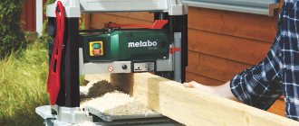
The principle of operation of a thickness planer for carpentry
The lumber is stretched relative to the horizontally located carpentry table. Feeding is carried out automatically by rollers. The planing shaft rotates towards it. There are two cutting knives on it. Sometimes there may be 3. What is the principle of wood processing? The workpiece is pulled between a stationary table and a shaft. The rollers, in addition to automatically feeding, press the workpiece to the table. The pressing force is very large, because if it is insufficient, the workpiece will rise and the removal will occur more than necessary. The workpiece must have a rigid positioning.
Is it possible to make a surface planer from a planer?
This same topic also applies to misconceptions about the fact that you can make a surface planer from an electric planer. They simply take some kind of base, weigh an electric planer on it and pass the workpieces through. It doesn't happen that way. If you run the same workpiece through a surface planer 10 times, the thickness will not change, since the board is calibrated on the first pass and practically no removal occurs on the second pass. If we do not have a planing shaft with rollers, but just an electric planer, there is no limit to prevent the workpiece from rising a little. In any case, you will miss and the board will lie differently each time. Accordingly, you will eat unpredictably. We can limit ourselves to the fact that if we use an electric planer, then we need to move the front sole as high as possible, stick on porous rubber, and be sure to make a metal ski. It will press the workpiece to the base. Only in this case will there be something like a surface planer. This is the only option.
Is a thickness planer capable of leveling workpieces?
The next question concerns leveling the workpiece; a surface planer cannot perform this function. This task can only be accomplished on a jointer. This is ensured only due to the fact that the board passes freely without deformation on perfectly leveled tables. Only protruding parts are photographed. When we run a board through a thicknesser, it becomes greatly deformed. The rollers press her to the table, even if she was hunchbacked, she straightens up. After the board comes out of the planer, it bends again and takes on its original form. This explains the fact that if you fill a thicknessing propeller, then at the output you will get the same propeller, only calibrated. Also sabers, skis and similar curved parts.
Suggestion in the video from the fifth minute on how and which thicknesser to choose in order to install it in the carpentry (at the beginning of the article).
Review of the Warrior 206 thickness planer
Thicknesser DeWALT DW 733. Characteristics and settings
Electrical equipment of the single-sided thickness planer SR-6-9
Location of electrical equipment on the thickness planer SR 6-9 Fig. 16
Electrical equipment of the machine. General information
The electrical equipment of the single-sided thickness planer CP6-9 (Fig. 16) contains:
- Ml - electric motor for driving the knife shaft;
- M2 - electric motor for driving the table feed and movement;
- Em1 - brake electromagnet of the blade shaft drive;
- Em2, Em3 - electromagnetic couplings for table movement;
- Em4 - electromagnetic brake clutch for table movement;
- Control equipment, alarm system - located in the control panel and the electrical cabinet niche
The following voltage values are used on the machine:
- power circuit 50 Hz, 380 V;
- control circuit 50 Hz, 110 V;
- signaling circuit 50 Hz, 24 V.
- power supply circuit for electromagnetic couplings = 24 V.
Electrical circuit diagram of thickness planer SR 6-9 Fig. 17
Description of the operation of the electrical circuit
List of elements for the electrical circuit (see Table 6). Before turning on the machine, it is necessary to open the electrical cabinet door and check the condition of switch B2 and fuses Pr1...Pr3, and then close the electrical cabinet door.
Voltage is supplied to the power circuits and control circuits by turning on the input switch B1. At the same time, the milky-colored signal lamp L1 on the control panel should light up. The knife shaft drive is turned on using the Kn5 button. In this case, the magnetic starter P1 is turned on, closing its contacts in the power supply circuit of the electric motor of the knife shaft. The knife shaft drive is turned off using the Kn4 or Kn1 button.
The knife shaft drive cannot be turned on when the exhaust hopper is open or the side cover is open (right and left). The blocking is carried out by microswitches B4, B5, B6.
The feed drive is turned on by button Kn6 when the knife shaft drive is turned on. In this case, the magnetic starter P2 is turned on, closing its contacts in the power supply circuit of the electric motor M2. The feed drive cannot be turned on if the knife shaft drive is not turned on, due to the presence of the closing contacts of the P1 starter in the power circuit of the P2 starter coil.
The table is moved by turning on the Kn2 or Kn3 button in jog mode with the knife shaft drive turned off. When the knife shaft drive is turned on, the table movement drive will not turn on, since its circuit contains a break contact of the magnetic starter P1.
The Kn2 button turns on relay P3, which closes its contact in the power circuit of the electromagnetic clutch Em2 and turns on the upward movement of the table.
Button Kn3 turns on relay P4, which closes its contact in the power circuit of the electromagnetic clutch Em3 and turns on the drive to move the table down.
To fix the table in a given position, an Em4 brake clutch is used.
Switch B3 is used to turn on the local lighting lamp L2.
The Kn4 button, located on the control panel, and the Kn1 button, located on the machine frame, serve for emergency shutdown of the machine.
Protection of electrical equipment from short circuit currents and overloads is carried out by the input switch B1, switch B2 and fuses Pr1...PrZ.
Zero protection is provided by magnetic starters.
Preparation of the electrical equipment of the machine for initial start-up and initial start-up.
When initially starting up the machine, it is necessary first of all to check the reliability of grounding and the quality of installation of electrical equipment by external inspection. After inspection in the electrical cabinet at the terminal blocks, disconnect the power wires of the motors Ml and M2. Turn on the input switch B1. Using the buttons located on the control panel, check the precise operation of the starters. Then restore the circuit to its original position and check the correct direction of rotation of the electric motors.