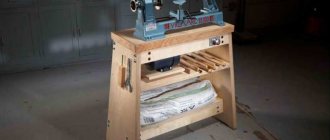
The device of a wood cutting machine
Structurally, the machine consists of several main components:
- Bed; made of low-grade steel by casting; vertical posts can be long or short supports. In professional devices that have a gearbox, an additional shaft for uniform movement of the cutter, other devices, long bed posts; the engine and transmission elements are attached to them. In simpler devices, the workpiece is attached to the motor shaft, the frame has short racks. The machine is placed on the table;
- Headstock; on one side, torque from the engine is transmitted to its shaft, on the other, the workpiece is attached; in the simplest case, this is a continuation of the electric motor shaft with a device for fastening the workpiece;
- The tailstock performs several functions: supports, centers the other end of the workpiece; provides fixation of its position depending on the length of the workpiece, movement of the centering cone along the horizontal axis, its rotation (in some cases) together with the workpiece, and locking against untwisting;
- Electric motor; power and speed are selected depending on the weight, size of the workpieces, and machine design; on devices with direct drive, a low-power, low-speed motor is installed;
- The stop for the incisors is a tool rest; copier
Work principles
The common element for all copy routers for wood or metal is the milling cutter - a cutting and processing tool.
Key points of operation of the milling device:
Using a copier, a surface or contour is specified, which is then followed by a cutter.- Between the tracking unit and the cutting cutter there is a system connecting them. When processing wooden products, it most often has mechanical control and feed. In addition to the mechanical system, a pneumatic or hydraulic system is used.
- The copier can be either a flat template, or a reference volumetric blank, a photocell or a drawing. CNC is built into complex machines, and then they become widely universal.
- The parts that act as templates can be made from anything. It can be wood, metal, plastic or other dense material.
All copying machines operate on the same principle: a tracking device is connected to a sample of any type, which, through a connecting system, transmits the necessary direction and force to the cutting unit - the milling cutter.
The use of a sample template eliminates manual intervention and therefore, even when making copies of complex parts, all resulting products are the same in shape and size. Copy milling can be contour, volumetric or direct. The workpiece being processed and the initial template are fixed on the moving working surface of the machine.
When contour copying, the working surface moves in the longitudinal direction. In the second case, during volumetric copying, the table with the copier and the workpiece are movable in both the transverse and longitudinal directions.
The unit between the copier and the cutter, which precisely sets the movement and force of the cutting tool, is called a pantograph. On wood or other materials, pantographs work equally flawlessly.
The pantograph is used in direct action machines. This unit allows you to organize not only copying, but also scaling of parts. Often such machines are used for engraving work.
The pantograph consists of a guide pin, its axis, a separate axis of rotation and a tool spindle. The guide pin and the spindle are placed on one bar. The copying scale directly depends on the ratio of the spindle arms and the pin.
The finger moves along the contour of the original and sets in motion the rack, which rotates freely on an axis. Thus, the spindle located on the other side of the rack follows the movement of the finger.
The cutting edge is driven by a screw, a spool valve, a solenoid, and an electromagnetic clutch. A relay is used in the amplification device of a metal copy milling machine. It can be electromagnetic, hydraulic or electro-optical.
Rotation is transmitted from an electric motor using a chain and a hydraulic cylinder.
The transmission of torque can be multi-stage.
The quality of the part obtained by copying, namely roughness, dimensional and shape accuracy, directly depends on the speed of response and movement of the tracking device. Good results are considered: profile accuracy is two hundredths of a millimeter, and the roughness must correspond to the sixth number of generally accepted standards.
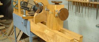
Manufacturing sequence
To make the machine reliable, convenient, and durable, adhere to the following plan:
- Find out which workpieces need to be turned: length, diameter, material, shape features, quantity; this information determines the choice of product components: their dimensions, strength, design features;
- Determine the type of drive: direct, with a belt drive, with a gear transmission; choose a design option: floor-standing, table-top device;
- They find out what materials and parts are available, what can be used from old, unnecessary mechanisms, and what needs to be purchased;
- Draw sketches of individual parts and assemblies indicating dimensions;
- A frame is welded from sections of angles and channels; the simplest option is a desktop machine with direct drive;
- Install the engine; on its shaft there is a device for centering and fastening one end of the workpiece;
- The tailstock is made and installed on the bed;
- They weld the tool rest, cut out the copier, and fasten them near the bed;
- The device is tested and modified if necessary.
Features of operation and safety precautions
The operating principle of copying and turning equipment is simple:
- the blank of the future product is clamped in a horizontal position;
- the machine is started, which rotates the workpiece around an axis;
- the cutter removes excess wood from the workpiece, giving it the required shape.
To avoid injury during work, you must follow basic safety rules:
- Do not expose or remove the workpiece from operating equipment.
- Do not lean or press against the machine while working.
- Remove chips only with a special brush.
- The machine must not be left unattended during operation.
- The technician must wear safety glasses to prevent chips from getting into his eyes.
A turning unit with a copier is successfully used both in large mass production and in home workshops for the manufacture of identical products. You can make such a machine yourself, having an unnecessary hand router, a sheet of plywood and horizontal bars of a certain size.
Tools, actions with them
They begin work by marking the sections of the corner and channel for the frame; To do this, use a tape measure or marker; for drawing perpendicular cutting lines - a square. Using a grinder, cut parts to the required length.
An abrasive wheel is used to remove rust and dirt from the surface of parts along the joints to improve the quality of the weld.
- On the welding table, the workpieces are placed in the required configuration, the value of the right angle is controlled, and they are pressed to the surface with clamps.
- Boil the joint on both sides and repeat the operation for all joints. Use a grinder with an abrasive stone to clean and level the weld seams.
- On the finished frame, markings are made for mounting the engine, and with a punch, recesses are made in the place of future holes.
Using a drill, holes are drilled first with a drill of small diameter (3-4 mm), then with a large one (9-10 mm). The tool rest is made with the same tools. To manufacture some parts of the headstock and tailstock, a metal lathe is required.
It’s easier to order a shaft, thrust cone, and bearing housings from a professional turner. You can simplify the tailstock to the limit: use a long screw with a conical point.
The copier is made from plywood. A marker is used to mark the profile line of the future product, and a cut is made along it with a jigsaw.
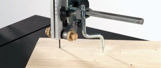
- The copier is mounted at the level of the tool rest. A limiter is installed on the turning cutter, moving along the edge of the copier.
- Wooden pulleys for a drive with a belt drive are made like this: a disk of the required diameter is cut out of a hardwood board and placed on the motor shaft.
A temporary tool is prepared, the engine is secured, started, and a pulley is machined on it. It will be accurate and balanced.
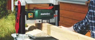
Capabilities of copy-milling equipment
The copying machine, which belongs to the milling group, is designed for copying and milling work with flat and three-dimensional parts. In addition, such a device can be used to engrave shaped profiles, apply inscriptions and patterns (even of high complexity) to products, and carry out light milling operations on wood and other materials.
An example of the result of a copy-milling machine
Using tools with cutting parts made of various materials, parts made of cast iron, different types of steel and non-ferrous metals are processed on copy milling machines. Such devices for producing parts in small and large batches successfully produce blades for turbojet engines and steam turbines, propellers for ships, cutting and forging dies, impellers for hydraulic turbines, molds for pressing and casting, molds, etc.
A copy-milling machine performs technological operations that are practically inaccessible to universal equipment. The operating principle of such a machine is based on the copying method, for which a special template is used. The use of a template eliminates the human factor when processing even the most complex parts, due to which all finished products have the same shape and geometric dimensions. Conveniently, one template can be used to accurately manufacture a large batch of parts that will be completely identical to each other.
In order to copy the shape and dimensions of the template as accurately as possible, a copier (pantograph for a router) is installed on a copy-milling machine. The purpose of such a device is to accurately transfer all movements from the copy head to the cutting tool.
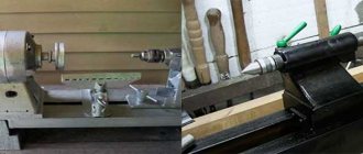
Mini wood cutting machine
This device is useful for creative work, creating complex products from small round parts. One of the common options is a machine made from a drill.
Attach the drill to the base; instead of a drill, insert a rod with a plan washer into the chuck. The tailstock is a long pointed screw.
Motors from old household appliances are often used to drive a mini-machine:
- Washing machine, reel-to-reel tape recorder;
- DC motors from a car heater and windshield wiper drive are suitable.
This device is successfully used in everyday life for polishing the surface of parts after repairs, removing old coatings, and applying varnish.
Purpose
Often, a copy-milling machine is used to perform volumetric and plane processing; its operation is similar to those on which the CNC system is installed. At the same time, special models allow wood processing to be carried out in volume when a volumetric model is used as a copier. In the woodworking industry, volumetric processing allows:
- create ornaments and various inscriptions.
- engrave shaped profiles.
- create complex patterns, the edges or planes of which are located in different planes.
The woodworking machine in question is often used in furniture production. Many decorative parts that have complex shapes are created using a similar machine.
Photo of a wood lathe
Examples of manufacturers
Those who need a reliable machine for flat milling should pay attention to the products of the Italian company GRIGGIO. Machines of this brand have a relatively low price and are a good solution for creating shaped parts, skirting boards, and trims. With their help it is convenient to create facades of furniture panels and wooden doors.
The VFK-810 milling machine with a table rotation angle of 45 degrees is perfect for those who are interested in making furniture. Its distinctive feature is the high speed of rotation of the cutter (up to 20,000 rpm), which guarantees excellent surface quality of the finished product.
The Chinese MX 5068 unit has comparable characteristics at a much lower price. It boasts a cutter rotation speed of up to 18,000 rpm and uses a pneumatic drive for table rotation and tool movement.
Those who are planning to take up carpentry seriously should pay attention to a milling unit made in Taiwan. WINNER LH-1000 will be the best assistant when it is necessary to mass produce similar parts. A special feature of the machine is a multi-level spindle, which allows you to perform several operations at once in one pass and create a product of the required profile without the need to rearrange the cutting tool.