A manual wood router is a truly universal machine. In capable hands, it can replace most of the machine park with a well-equipped carpentry workshop. Considering that the price of a hand router is quite affordable for every home craftsman, and replacement cutters are sold both in sets and individually, the need to have such a universal tool in your arsenal is obvious.
Specific working techniques are also available that are characteristic only of a manual milling machine and are impossible on “large” machines. The question is interesting and capacious, so it should be considered in detail.
What is a router and what is it for?
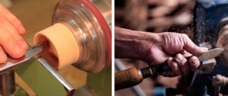
A hand router is a power tool, which is an electric motor with a collet for installing a cutting tool on a shaft.
Integrated with it is a platform or base, a kind of desktop, which is capable of moving along guides and being fixed in a given position.
Using the platform, the cutting depth is set. There are two handles on the sides, by which the machine is held in the desired position or applied to the workpiece.
The milling cutter is designed for cutting parts made of different materials:
- Solid wood;
- Chipboard, including laminated chipboard;
- MDF;
- Fiberboard;
- Aluminium, duralumin;
- Soft plastic.
Using a hand router, different types of material processing can be performed. These include the following operations:
- Milling of recesses of various shapes - grooves, sockets, grooves and other elements;
- Profiling edges - creating shaped (curly) surfaces, milling quarters;
- Milling of special structural elements - recesses for hinges, locks, handles, tenons and sockets for them;
- Trimming curved and complex edges of furniture parts or special elements.
To ensure the accuracy and cleanliness of the cut, the design of the router has a lot of adjustment and adjustment elements. With their help they produce the following
- Changing the shaft rotation speed;
- Setting the immersion depth of the cutting element;
- Pre-set depth for quick cutting mode changes.
Important! For mass production of large volumes of products, a manual milling machine is not suitable. It is most rational to use it only for domestic purposes or in small workshops engaged in small-scale production of custom-made products.
Cutter selection
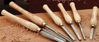
Depending on the type of processing, various wood cutters are used for a hand router; there is a wide choice:
- cylindrical;
- disk;
- end;
- conical;
- folded;
- fillets;
- moulding;
- profile.
Cylindrical cutters for wood processing create grooves and cuts of various configurations. They are used for cutting parts, creating blind and through holes. With their help, tongue-and-groove joints are made on the mating parts with exact matching sizes and configurations.
The easiest way to cut a groove with a manual wood router is to use a disk cutter. The tool is selected in width equal to the thickness of the key. Grooves of any length are cut in one pass. The distance to the plane is adjusted by the sole and stops. On a lamellar machine for processing wood, the angle of inclination, distance from the end and height are set using stops on the sole and automatically, without marking, an exact match of the grooves for the key is ensured. The assembly of mating parts is carried out without displacement or distortion.
Specialists who know how to work with each type of cutter and what templates to make make the complex dovetail joint using hand-held equipment.
When figuring out which cutters can do what when processing wood, you should pay attention to the shape of the cutting edge. In a rebated one, it is wide and even. In one pass with low feed, you can select a quarter. The disk one can do this job in 2 moves. It must be rearranged after the first cut at a right angle. But rebate cutters for wood processing transform everything into chips. After the disk, square slats remain, suitable for use.
Fillet, molding and profile cutters are all shaped cutters. When carving wood with a router with your own hands, the end takes on a shape opposite to the configuration of the cutting edge. The fillet chooses a quarter radial shape. A moulder with an oppositely shaped cutting edge makes a beautiful radius instead of an angle.
Electric milling machines with complex configurations are used for the manufacture of skirting boards and baguettes, carved edging for cabinet furniture.
In a home workshop, cutters for a beginning carpenter should be simple in shape and small in diameter. They experience less wood resistance during processing. The router is easier to control. After mastering simple operations of cutting grooves and cutting out straight parts, you can move on to complex woodworking techniques.
Main types of nozzles
Main types
For milling work, end mills with a shank diameter of 6.8 or 12 mm are used.
They are sold individually or in sets that include the most popular types of cutters.
There are sets with 7 mm shanks, but it is difficult to find a collet for them. Depending on the purpose and shape of the cut, there are edge and groove cutters. Edges include:
- Profile;
- Conical;
- Moulded (moulded, quarter-rolled);
- Disk;
- Fillet.
A common feature of edge cutters is the presence of a bearing that acts as a stop. Groove cutters include:
- Rectangular (straight);
- Filling;
- "Dovetail";
- V-shaped.
Groove cutters do not have thrust bearings and allow you to cut both on edges and on faces. There are straight cutters with a bearing at the top, just above the cutting edges. Usually its diameter corresponds to the size of the cutting part, which allows you to cut curved shapes according to a template. Such cutters are called turning cutters. They are not included in standard kits; if necessary, they must be purchased separately. Almost all cutters are available in several standard sizes. To make a recess of the required size, you need to select a cutter of the appropriate diameter or profile.
Wood carving with milling machines
A CNC milling machine produces flat-relief threads. This type of work is performed in several ways:
- "in body";
- cut flat-relief;
- with the outer wall half formed;
- with the formation of the outer wall completely;
- combined.
The cut out design can serve as decoration, or play the main role of the composition. When creating a design for CNC machines, you need to take into account technical and artistic compositional features.
The formation of drawings requires compliance with a number of rules:
- the background part should not be too small compared to the size of the cutter used;
- It is not recommended to use too wide lines;
- the composition should contain a minimum number of sharp corners (in large quantities they create a complex ornament, which not every CNC machine can handle).
The quality of the tool used is an important factor in giving the drawings accurate shapes. During operation, a large load is placed on the tool. A low-quality device will wear out quickly.
The highest quality are engraving cutters, also known as engravers.
These devices have similar characteristics, but differ in angle of inclination.
In second place in popularity are cylindrical end mills. The advantage of such a tool is the ability to trim threads along the established contour.
Types of cutters
The most popular and high-quality cutters, characterized by high productivity, are made:
- Israeli company Dimar;
- American company SGS Tool Company.
The first type is represented by carbide replaceable engravers. Thanks to this device, you can get high-quality flat-relief engraving. It is recommended to use holders for engraving. CNC machine equipment equipped with holders allows for more precise lines. It can handle hard wood.
Preparation
To install the cutter in the chuck, the router is laid on its side. Some types allow you to disconnect the engine with the cartridge from the platform without changing its settings. Others do not provide this option, so most often you have to lower the base as far as possible. The cartridge is unscrewed using a wrench, which is included in the package.
The cartridge is fixed in immobility using a special button located above the point where the shaft exits the housing. It is not present on all types of milling cutters; sometimes you have to fix the shaft with a wrench and unscrew the chuck with another.
It is not necessary to remove the union nut completely, but sometimes this has to be done if the cutter is clamped too tightly in the collet. By gently tapping on the side surfaces and turning the shaft, the collet is loosened and the jammed cutter is removed.
The nut is screwed on, the new cutter is inserted into the collet approximately 20 mm. Some cutters on the shanks have special marks indicating the minimum and maximum immersion depth, but most of them are installed by eye. If the installation depth is too small, sharp feed may cause deformation of the cutter and damage to the workpiece. This is dangerous, since the maximum rotation speed of the router shaft is 30,000 rpm or more. A cutter flying out of a collet while moving has great destructive power; if it hits a person, the consequences can be very undesirable.
Attention! It is prohibited to screw the union nut without a cutter installed, as this will break the collet.
Setting the milling depth is as follows:
- The router with the base lowered is installed on a flat platform;
- The cutter is lowered all the way and fixed;
- The depth indicator slider is set to zero;
- The depth stop is raised to the required amount and locked with a screw;
- The cutter is unlocked and lowered until the depth stop stops against the adjusting screw, after which it is fixed again.
It is recommended to check the set depth on a test piece so that adjustments can be made if necessary. You should not immediately make the depth too large; this will cause the router to overheat and create an excessive load on the electric motor. The recommended depth per pass is 4-6 mm.
Contents (Updated) 1. Types of flat-relief carvings made on CNC machines. 2. Rules for constructing drawings. 3. Creating a vector model (drawing) in the CorelDRAW X7 program. Technology and overview of the necessary tools in CorelDRAW X7. 4. Cutters used. Description of technology. 5. Creating a control program for flat-relief threads in ArtCAMPro 9. 6. Possible defects when milling flat-relief threads on CNC machines and methods for its prevention. 7. Practical work. Creating a program for CNC (creating a vector model of a thread element in CorelDRAW X7, creating a control program in ArtCAMPro 9). Thread visualization. 1. Varieties of flat-relief carving performed on CNC machines. Flat-relief carving, performed on CNC machines, can be divided into several types. Carving in the body. This technology implies the following. The background of the thread drops slightly from the top point of the workpiece by 4-5 mm. Depending on the size of the pattern, the outer wall of the thread is removed with a 30 - 60 degree engraver (cutter). The center lines and all the various internal decorative elements of the design (petals, slots, etc.) are milled with a 90 - 120 degree engraver (cutter) See Fig. 1;2.
Slotted flat-relief carving. Slotted flat-relief carving, in turn, can be made in several variations. The background is selected completely at right angles from the top point to the very bottom of the thread using a cylindrical end mill. See Figure 3.
The outer wall of the thread is formed in half, or to a certain part, with a 30-60 degree engraver. Next, the rest of the background is removed (milled) with a cylindrical end mill. The carving is obtained with a so-called sole. See Figure 4.
The outer wall of the thread is formed entirely with a 30-60 degree engraver. See Figure 5.
Also, the slotted thread can remain in a specific frame and be part of the joinery structure. See Figure 6.
Or be an independent element and invest in an already prepared recess (selected background, ark). See Figure 7.
It should be noted that you can combine different types of flat-relief carving to obtain an interesting design solution. See Figure 8.
3. Rules for constructing drawings . When creating designs for flat-relief carving made on CNC machines, you should adhere to a number of technical, artistic and compositional nuances. Technical aspects consist in the conformity of the drawing with the possibility of milling it on CNC machines using the engraving method. For example, the thread backgrounds selected should not be too small for a cylindrical end mill. See Fig.9.
The center lines of the thread should not be too wide, because this will make them too deep with the centerline milling method. If the thread is slotted, then the thread elements should not be too thin or protruding, because chipping of these elements is possible. If the task is to quickly mill a thread, then the pattern should be drawn in the following way so that a minimum number of cutters are used when milling the backgrounds. This will save time on changing tools. Artistic and compositional nuances. When creating a design for flat-relief carving, it is necessary to pay attention to the aesthetic component: maintain composition, rhythm of the design, consistency, completeness in construction. All weaves in the pattern must alternate correctly and logically (top-bottom-top) See Fig. 10.
In the process of drawing, you need to avoid breaking the lines of the drawing (especially at intersections), maintain parallelism of the lines, and ensure that the middle line in the thread drawing is exactly in the center. It’s easier to draw drawings by hand on paper, then scan them and convert them into vector in CorelDRAW. Below you can see examples of drawings. See Figure 11.
The 3-Point Curve, Polyline, Bezier, Pen, and B-Spline tools are ideal for quickly converting a drawing into a vector. It is advisable to use this arsenal of tools with bindings enabled (for automatic merging of nodes). See Figure 14.
It should be noted that the “Curve through 3 points” tool is convenient if the quality of the traced (created) pattern is good. The “Contour” tool is very convenient and necessary for automatically constructing straight middle lines. This tool can also be used to build the shape of the entire thread. The Outline tool is indispensable when the drawing being translated is of very poor quality. See Fig. 15.
Use the Smart Fill tool to automatically create a closed new object from intersecting objects. Because the vector model of the future carving is built only on the basis of closed objects (this is a logical necessity for creating a control program based on engraving in ArtCAMPro 9), the “Smart Fill” tool greatly speeds up and simplifies the process of converting the drawing of the future carving into a vector. See Fig. 16.
The Blend tool is essential and very practical for creating an array of objects. Using this tool, it is possible to automatically distribute objects in one line or along a certain path (curve, circle) See Fig. 17.
The Transform tool is convenient for automatically copying and distributing objects either along one line or by rotating them around an axis point. See Fig. 18;19.
The Lens tool is effective for quickly cutting up a large collection of vectors and then creating a copy of them. See Fig. 20.
The Remove Virtual Segment tool allows you to quickly remove an unnecessary vector segment that is visually (virtually) formed by the intersection of other vectors. See Fig. 21.
The Knife tool is needed to cut an object. Moreover, when cutting one closed object, two independent closed objects are obtained. Convenient for trimming (editing) center lines in thread elements. See Fig. 22.
Technology for creating a vector thread pattern. When converting a drawing into a vector or creating a vector drawing from scratch, you need to adhere to certain simple rules (logic). Compliance with these rules will allow you to obtain a carving program in ArtCAMPro 9 using the engraving method. You need to create a vector in such a way that the entire drawing consists of closed independent elements (vectors), but when they are added, the illusion of the integrity of the drawing is created. See Fig. 23.
All elements of a vector drawing should not intersect or touch each other. The center lines should slightly (up to 1 mm) not reach the intersection. See Figure 24. 4. Cutters used. Description of technology.
It should be immediately noted that the quality of the tool that is used on CNC machines for milling flat-relief threads is very important. It is highly recommended not to use a low-quality tool from an unknown manufacturer. From my own experience, I can say that using a low-quality tool can lead to a number of problems. For example, with rapid wear of the cutting edge of the tool, non-compliance with the declared geometry of the tool, poor quality of surface treatment of the workpiece, excessive chipping during processing, excessive raising of pile during processing, etc. Types of cutters used for engraving threads. First of all, these are engravers (engraving cutters). The following engravers are used: 30? - 60 degrees, 90 and 120 degrees. See Fig. 25-26-27
Cylindrical end mills with a flat base with a diameter of 1 mm to 8 mm are also used. Engravers select the lateral inclined walls of the thread, the middle lines, petals, and undercuts at intersections. Cylindrical end mills are used to select backgrounds; these cutters are also used to trim threads along the contour if necessary (if the thread is overhead or slotted). See Fig. 28
Based on personal experience, when engraving flat-relief threads on CNC machines, I suggest using the following cutters. Dimar company, country of origin: Israel. And it is their new line of carbide replacement engravers. See Fig. 29.
It is advisable to have several holders for engraving plates 30-60-90 degrees. These engravers can mill the center lines, petals, and side walls of the thread. Also, for milling the sidewalls of carvings for hardwoods (maple, ash, oak, hornbeam), I would recommend an all-solid engraver with three cutting knives. See Fig. thirty
For sampling backgrounds and for cutting along contours, I recommend cylindrical end mills with a flat base from SGS Tool Company. 2-way for cutting and 3-way for sampling blind backgrounds. Country of origin: USA. 5. Creating a control program for flat-relief carving in ArtCAMPro 9. These recommendations will also be relevant for later versions of ArtCAM. After the drawing of the future thread is created in CorelDRAW X7. It must be exported to Adobe Illustrator 8.0 format. Next, in the ArtCAMPro 9 program, create a new model with the necessary parameters (height, width, resolution). See Fig. 31-32
, Import the previously saved vector drawing into ArtCAM. “File” - “Import” - “Import vectors” See Fig. 33.
Often the engraved design consists of a large number of elements to which different engraving methods will be applied. For the following reason, it is more advisable to arrange the drawing in layers. This will also help to quickly change certain engraving parameters (plunge feed, working feed, safety plane, etc.). For example, when milling a thread in a body (not through), you can create the following layers with the names: “Middle lines”, “Backgrounds”, “Petals” ", "Pruning". In order to create a new layer, you should have an attached “Vector” window in the right corner of the screen. See Fig. 34. (If this window is missing, press the F7 key on your keyboard)
, In order to create a new layer, you need to click the leaf icon (the first one in the left corner of the attached window) See Fig.35
Next, give the required name to the new layer; to do this, double-click the left mouse button on the layer name and enter the name. See Fig. 36.
Next, select the thread elements one by one (holding the Shift key) and move them to the desired layer according to the logic. Right-click on the selected objects, then select the “Move to layer” menu item, then select the desired layer from the drop-down list. See Fig. 37
,
Note! Also notice the light bulb icon next to the layer name. By clicking on this icon, you can enable or disable the display of vectors located on this layer. It is very convenient for group selection of the desired vectors using the lasso method. See Fig. 37(2)
Once the vectors have been laid out into layers, you can proceed directly to creating control programs. Let's look at the use of engraving tools in ArtCAMPro 9 using a practical example. You can download a vector drawing for completing a practical task for free here. See Fig. 38
Engraving backgrounds.
Turn off all layers, leaving only the “Backgrounds” layer. See Figure 39.
Next, we will diagnose the vectors for errors (checking for intersections, coincidence of vector points, the presence of loops). To do this, select all the vectors related to the backgrounds by throwing a lasso with the left mouse button, then in the top text menu select the “Vector” - “Vector Diagnostics” tab. See Fig. 40
Next, click the “Detect” button, uncheck “Save original”, then “Correct errors”. Errors that could not be corrected automatically are corrected manually. See Fig. 41
The next step is to select the “NC” tab from the bottom left - 2D NC, then the “Engraving” tool. See Fig. 42-43
Next, we create a list of tools that will be used when engraving this ornament (the “Add” button). In this particular case, this is a cylindrical end mill with a diameter of 1 mm (for milling backgrounds) and a 30-degree engraver for forming the walls of the thread. See Fig 44
Let's set up each of the cutters. First, the general parameters for all cutters are “Initial pass”, “Finishing pass”, “Accuracy”, check the boxes next to the parameters “Vectors on the surface”, “Cylindrical tool offset”. It is also necessary to set the “Safety height” parameter (individually, depending on how the workpiece is secured and how much the equipment protrudes) See Fig. 45
Next, we will set up a cylindrical end mill with a diameter of 1 mm. Let’s set up parameters such as “Step”, “Depth per pass”, “Working feed”, “Plunge feed”, “Rotation speed”, “Allowance”, “Machining strategy”. And we will also indicate the thickness of the material being processed. After setting all the parameters, do not forget to click the “Calculate” button UE See Fig. 46.
Next, let's set the engraver to 30 degrees. Let's set the following parameters as “Step”, “Depth per pass”, “Working feed”, “Plunge feed”, “Rotation speed”, “Allowance”, “Machining strategy”. Also, be sure to check the box next to the “Cutting corners” option. I would also like to pay attention to the next parameter as “Profile only”. Set this parameter if you do not want the engraver to clean up the background behind the cylindrical cutter. For numerical settings of the engraver, see Fig. 47.
To make sure that all cutters are configured correctly, make a visualization (simulation) of the UE. To do this, select “UE” in the top text menu - “Simulation of all UEs” See Fig. 48
The next step is to set up the cutter to cut the center lines. Let's turn off the display of the UE, and also turn off the layer with the backgrounds. In ArtCAMPro 9, select the 2D NC tool “Engraving along the center line” See Fig. 49
Next, we will select an engraving tool, in this case it is a 90 degree engraver (it should be noted that if you want to get deeper center lines, then select a 60 degree engraver), then we will configure the necessary parameters of the cutter and the “Center Line Engraving” tool. See Fig. 50.
Next, we calculate the maximum depth and width by clicking the “Middle Line” button. See Fig. 51
The next step is not to forget to calculate the UE. The final stage for this practical example is the formation of intersections of the so-called “cuts”. Hide the layers containing the backgrounds and midlines. Let's leave only the layer containing non-closed vectors that will form clippings. See Fig. 52
Next, select the 2D NC tool “Profile Processing”. Let's select the required cutter. In this case, it is a 30 degree engraver (the same as when engraving the background), the milling depth is 1.2 mm. The rest of the instrument settings are as in the figure. See Fig. 53
It should be noted that sometimes the vectors need to be rotated to form intersections so that the cutter passes on the side of the vector we need. In order to expand a vector, select it, then right mouse button, in the menu that appears, select the “Expand vector” item. See Fig. 54
Launch the final visualization of all UEs. If you did everything correctly, you should get something like in the picture. See Figure 55
Basic rules of use
In this chapter we will try to answer the question: “How to work with a hand router correctly?”
A high-quality result is possible only if certain rules and working conditions are observed. These include the following wood carving requirements:
- It is necessary to work only with a sharp tool. If the treated surface is burnt, fleecy or has many small chips, the cutter should be replaced;
- The workpiece must be securely secured using clamps or other devices. You cannot hold the workpiece in your hands;
- The feed of the router should be smooth and leisurely, without jerking. Do not try to immediately remove a thick layer of material. In some cases, the excess mass is pre-drilled in order to remove a small remainder with a milling cutter;
- The cutting tool is changed only when completely disconnected from the network.
Example of table top milling:
Compliance with these requirements should become a prerequisite for work for a home master.
The cleanliness of the cut is ensured not only by the degree of sharpness, but also by the cutting speed. The higher the number of revolutions, the cleaner the processed surface. For hard materials - aluminum, dense wood, etc. — the shaft rotation speed should be reduced slightly so as not to overheat the cutting edges of the cutter.
When milling edges, the feed is made so that when moving away from you, the part remains to the left, and vice versa. If you need to make a groove, the direction of movement does not matter.
Let's look at common techniques for working with a hand router.
How to cut a circle
In order to cut a circle with your own hands using a router, you need to use special templates or devices.
First of all, it is necessary to clarify what exactly is meant - you need a part in the form of a circle, or a hole.
The delivery set includes a parallel stop.
If you drill a hole in it, you can make a simple circular jig. You need to turn the stop upside down, screw it in the center of the future circle onto a screw, use clamps to set the desired diameter of the hole and cut it in a circle. Sometimes the kit comes with a compass rod, which makes it even easier to make round holes.
When a circle is needed, a template should be used. It is a sheet with a hole of the required diameter. It can be made from plywood or fiberboard, which is recommended to be glued in half. This will result in a stiffer and thicker sheet, from which a high-quality template will come out.
The diameter of the template depends on how the emphasis will be made. If you rely on the base itself, then the diameter of the template should be increased by the amount of the platform radius plus the radius of the cutter. In cases where the emphasis is on the copy ring included in the delivery set, the diameter of the template is equal to the sum of the radii of the cutter and the outer convex part of the ring.
As a template, you can also use a ready-made circle into which the copy cutter bearing rests. The easiest way to fix it is with double-sided tape, after cutting off the excess material with an allowance of 2-3 mm.
The quality of work depends on the accuracy of the template. Usually it is cut out with a jigsaw, trying to maintain the shape as accurately as possible. In some cases, a round hole is cut using a jig with a clamped cutter.
Sampling quarter
Selecting quarters with a manual router can be done in several ways:
- Using a rip fence;
- Using an edge cutter with a smaller diameter bearing;
- With the machine platform resting on a flat bar, fixed at the required distance from the edge.
The first option is used when there is a smooth edge and a large quarter size that requires several passes. The second method is used to obtain the same quarter width, since only the immersion depth of the cutting part of the cutter can be adjusted. The third option allows you to make a large-sized quarter when the outer edge of the workpiece is uneven or unprocessed. Wide quarters have to be done in several passes, each time moving the stop a few millimeters until the desired width of the step is achieved.
How to choose a groove
To make a groove with a router, use:
- Parallel stop;
- A strip fixed at the required distance parallel to the groove line;
- A pair of planks between which the router platform moves.
The first two methods require accuracy and attention, since the milling machine can only be focused in one direction. If the master is distracted, the cutting line may go to the side. The third option allows you not only to avoid such situations, but also to increase the width of the groove. The distance between the slats can be increased slightly so that the width of the groove is equal to the diameter of the cutter plus the size of the gap. In this way, fairly wide recesses are made for various furniture parts, locks, and structural elements.
Edge processing, working with a template
For cutting edges, appropriate cutters equipped with a thrust roller (bearing) are used. It is necessary to pre-align the edge, otherwise the cutter will copy all the irregularities and the edge will look sloppy. In addition to edge cutters, templates are used to form a curved shape or produce a batch of identical parts. For work, a copy cutter with a bearing is used. The cutter is pulled out so that the thrust roller rolls along the template, and the cutting part processes the edge of the part.
Let's take a closer look at these working methods.
The width of the part is less than the length of the cutting part
In such cases it is necessary to use a template. The simplest option is to combine two identical parts into a pack. A bearing rolls along one of them, the other is processed by a cutting edge. If there is only one part, you will have to make a template from sheet material - plywood, MDF, chipboard or the like. It is important to accurately repeat the configuration of the part, to avoid the appearance of potholes or irregularities.
Many craftsmen do not like to resort to this method, since the template is often used only once and then thrown away. However, the quality of work is more important than labor costs. You should not spare time and effort, since it will be difficult or even impossible to eliminate defects after processing the edge.
The principle of operation of a manual milling cutter
To learn how to work with a wood router, you need to master the selection of basic cutting options and choose the right operating parameters. Milling lessons include:
- characteristics of wood of different species;
- choosing the type of equipment depending on the volume of work;
- correct selection of tools;
- setting cutting depth in one pass;
- speed adjustment.
The first operations must be performed on a small router. It is light, low-speed. It is easy to hold in your hands and guide along the markings. For beginning carpenters, it is better to learn on birch, aspen, and poplar. The wood is relatively soft, not resinous. Wood processing is easy and smooth. The cutting modes along and across the fiber differ little.
Rotation speed selection
The cleanliness of wood processing largely depends on the speed of rotation of the cutting edges. The larger it is, the smoother the surface will be. Beginners should not start with high speeds and feed of the machine. The milling cutter requires some skill. When working, you have to use force to hold it and direct it where it should be.
The manual router is adjusted using the adjusting knobs on the body. The choice is made based on the material, depth of cut and cutter diameter. Rotation speed of light models from 7000 rpm. Professional high-power handheld equipment can reach 24,000 rpm. Smooth adjustment is made with a round knob mounted on the body near the motor. Minimum speeds are used when engraving and working with large-diameter tools or milling to great depths. Light models cannot withstand prolonged use at maximum speed.
The cut along the fiber is cleaner; you can set the average value for the number of revolutions. Cross cutting chips the edges. Maximum speed is suitable for it. In this case, you should reduce the feed - the speed of movement of the cutter. The table shows the dependence of feed on load - tool radius at medium speed.
| Cutter diameter, mm | Cutting speed, mm/sec |
| 4 — 10 | 5 — 7 |
| 12 — 20 | 3 — 6 |
| 22 — 40 | 1 — 3 |
When processing pine and birch, the feed rate is selected according to a larger value. Considering the hardness of oak, beech, and walnut, you should move the tool slowly.
If you have a choice, you should purchase equipment with a soft start function. Otherwise, you need to turn on the engine idle and then start working smoothly.
Securing the cutter
During the work process, the need to change the cutter constantly arises. It is more convenient to do this if you place the router on its side or place it on the top cover.
- Enable spindle lock. If the tool does not have such a function, unplug it and hold the spindle with a key.
- Unscrew the collet nut.
- Pull out the tool.
- Insert the cutter with the shank into the collet and tighten the nut.
- When working on a copier, install a copy sleeve.
- Turn it on and check at low speeds that there is no runout.
- Turn the router over and adjust the height of the cutter edge.
You can continue working. When replacing a tool, you must check whether it has a suitable diameter for the hole in the base of the tool.
Setting the milling depth
When cutting grooves and other operations, the milling depth must be precisely adjusted. For this purpose, there is a lift on the side of the case - a screw with a graduation scale. In professional models there are two of them, coarse and fine settings. This allows you to set the cutting depth with an accuracy of 0.01 mm.
First, the milling machine is placed on the sole and a zero value is set relative to the surface of the part. Then the elevator sets the desired cutting depth.
Common Techniques
A plunge router is a versatile piece of equipment that can perform a variety of operations. When working with equipment, the following techniques are used:
- leveling the surface;
- selection of grooves;
- edge milling;
- work according to the template.
Most often, in home workshops and enterprises, grooves are cut with a hand router. Depending on the location and shape, cylindrical and disk cutters are used. Their diameter and width correspond to the size of the key. Various devices are used for precise milling along markings.
When making any wood products, it is necessary to process the edges of the parts: leveling and giving a complex shaped shape. You can also mill the edge with a filler mill. The tool runs along the end, resting against the template with a bearing or rod. It cuts the side to size and creates a beautiful edge.
The most common technique is to work with a hand router using a template. The copying sleeve slides along the edge of the stencil, keeping the tool within its line.
Techniques for working with the template greatly simplify the implementation:
- keyways;
- curly cutouts;
- cutting parts;
- trim;
- decorative elements.
The template can be made from any material that is easy to cut: plywood, plexiglass, plastic. The cutout in the stencil is made larger; it is increased in each direction by the difference between the radii of the sleeve and the cutter.
Useful devices
There are a lot of devices that make working with a router easier and allow you to perform complex operations.
Most of them are designed to perform specialized types of woodworking, but there are also simpler ones that are useful for the home craftsman.
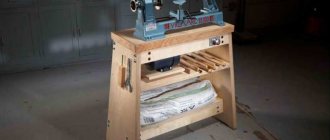
One such device is a table. The router is attached from below, the cutting organ passes through the hole and looks out. Working with such a table is reminiscent of processing parts on a stationary machine. You can install a stop, a clamp, or use a template. The advantage of this method is safety and the possibility of reliable control of the workpiece.
For copying on a scale, a pantograph or copying conductor is used. It can have a rather complex design in the form of a coordinate machine, or consist of several strips. A probe is attached to one end and is guided along a template. A milling cutter is attached to the other end, repeating all the movements of the probe and copying the reference part on its own workpiece.
There are also simpler types of devices, for example, a guide rail. It is a straight, even bar with a groove into which the ridge of the parallel stop is inserted. The tire itself is attached using clamps or double-sided tape. Useful when working with large-area parts, many grooves or other elements.
Devices for working with a manual wood router can be made independently or purchased ready-made. Factory templates are usually made of metal, durable and accurate. However, the prices for such products are quite high, which forces home craftsmen to make the necessary devices with their own hands.
Important! You should start making any additional devices after you have acquired some skill in working with a hand router and have an understanding of the meaning and necessity of having auxiliary devices.
In the video tutorial, the master teaches and shows what interesting things can be done with a hand router:
An addition to the device is the use of a router to create patterns.
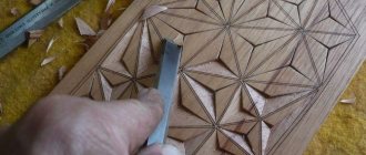
This small addition to the router's jig consists of a piece of plywood that is added to the base of the router. This base will help you add rounded corners to a door panel or other product. This method will help to obtain different corner radii by decreasing or increasing the size of the base. The creation of the device begins by making an equilateral triangle in the center of which a cutter is located. Keep in mind that the cutter at the base of the triangle must be positioned strictly in the center. Use a device that uses a router to create patterns as guides for the base. Start routing from any corner, move the router in a clockwise direction, and when one edge of the triangle touches the opposite corner, simply rotate the router to the adjacent side of the frame. Continue this all the way around the circle on the panel. This works best on hardwood or chipboard doors. If the doors are made of plywood, then the layers will stand out in the groove and this method is only suitable for painting the product with oil paint.
Safety precautions
Woodworking machines are the most dangerous type of equipment. A hand router is no exception. Working with it requires caution, accuracy and knowledge of safety regulations:
- Clothing should be sufficiently tight, without hanging ends, ties or other interfering elements;
- Wood dust is dangerous for the respiratory system and is a strong allergen. It is recommended to use a respirator, at least a regular “petal” one;
- Flying chips may get into your eyes. Most routers have a protective shield, but it would be a good idea to use glasses;
- It is necessary to hold the machine firmly in your hands. During operation, it vibrates and tends to turn in the direction opposite to the rotation of the shaft. You should not be distracted and let go of the running router;
- Recess the cutter shank into the collet by at least 20 mm and securely tighten the nut with a wrench;
- Before work, check the condition of the bearings on the edge cutters. They should not creak, wobble, or jam. If flaws are noticed, the roller must be replaced;
- First you need to start the milling cutter and wait until the working rotation speed is reached, and only after that insert the cutter into the material. If it is necessary to stop work, first remove the cutter from the material, then stop the machine;
- Always ensure that there are no nails or screws in the wood, and that there are no foreign objects or tools in the rotation zone of the cutter.
More detailed safety rules can be found in the user manual. Milling cutters from different manufacturers may have their own specific safety rules that you need to be aware of and follow during operation.
Edge processing - working with a template
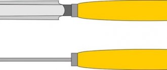
It’s easier and faster to process the edges of a regular board using a surface planer, but if you don’t have one, a hand router will also do the job, but it will just take more time. There are two ways: without a template and with a template. If this is your first experience with a router, it is better to use a template. When processing the edges of boards, you need straight edge cutters, and most likely you will need two - with a bearing at the beginning and at the end of the cutting part (pictured).
To process the edge - make a flat surface
As a template, you can use an already processed board or, for example, a building rule. The length of the template should be slightly longer than the length of the workpiece - 5-6 cutter radii on each side. This will make it possible to avoid the cutter “diving” into the material at the beginning and at the end. One important point: the horizontal plane (perpendicular to the one being processed) must be level. In any case, its curvature should not be greater than the gap between the bearing and the cutting part, otherwise the cutter will touch the template, and this is very bad - it becomes imperfect and the applied irregularities will appear on other copies.
If the width of the part is no more than the length of the cutting edge
The cutting part of the cutters is of different lengths, but the larger the cutting part, the more difficult it is to work - more effort has to be made to hold the unit. Therefore, it is easier to start working with a medium cutter. The procedure for processing an edge with a router (with a template) is as follows:
- Set the template so that it defines the required flat surface - stepping back the required distance from the edge.
- The workpiece with the template is securely attached to the table or any other horizontal surface.
- Install a cutter with a roller in the middle part. It is set so that the roller rolls along the template, and the cutting part rolls along the part. To do this, place the cutter on a fixed workpiece with a template, place the cutter disconnected from the network, adjust the position of the nozzle, and clamp it.
- Set the cutter to the working position - lower the body and clamp it.
- Turn on the hand router and guide it along the template. The speed of movement is determined by the depth of processing. You will feel everything yourself.
- How to operate the router? Pull or push? Depends on which side you are standing on. If the workpiece is on the left, you push, if it is on the right, you pull. You can also navigate by the flight of the chips - they should fly forward.
Read also: What are qualities and roughness parameters
That's all, actually. After you have completed the passage, evaluate the result and remove the clamps.
This, by the way, is another way to remove a quarter along the edge of the workpiece or in some part of it. To remove a quarter, adjust the cutting part so that the processing is at the specified depth.
Removed quarter on a furniture facade
By replacing the cutter with a curved one (fillet) and moving the template or using the included stop, you can apply a longitudinal pattern to the workpiece (pictured below).
The principle of working with a hand router is the same.
In general, this milling technique is quite convenient. For the first steps in woodworking, this is the best way to “get your hands on it”; then you will be able to straighten the edges even without guides.
A straight edge without a guide requires experience
The width is greater than the length of the cutting part
What to do if the thickness of the workpiece is no more than the length of the cutting part of the cutter? In this case, work with a manual wood router continues:
- Remove the template and use the same cutter again. Only in this case, the template will be an already processed part of the workpiece - the bearing will roll along the newly milled part. You rearrange the cutter so that you can process as much as possible. The protrusion of the holder will not allow you to move much, but you will still be able to process some part.
- After this, take another attachment - with a bearing at the end, turn the workpiece over so that the processed part is on the bottom. Secure it to the table with clamps. Install the attachment with the lower roller so that the bearing rolls along the machined part. This way you completely copy the already processed part.
The bearing rolls along the machined part, the cutting part levels the rest
Now the edge is completely processed on one side. If necessary, repeat with the second side. In general, to master working with a manual wood router, you will need several “rough” blanks. Choose from those that you don’t mind throwing away - at first there will be a lot of jambs, then gradually you will learn.
Obtaining a figured and curved edge
If you need not a straight edge, but a rounded one or any other shape of the edge, you need to look at the condition of the existing edge. If the workpiece is more or less flat, take the required edge cutter, install it and process the surface as described above. If the surface is too curved, it is first brought to normal condition and then milled.
This is necessary because the bearing roller rolls over the surface and if there are flaws, they will be copied. Therefore, act sequentially - first level it, then add curvature.
If a curved surface is at all boring, a template is cut out. The design is applied to plywood 8-12 mm thick; first it can be cut out with a jigsaw, so the edge can be brought to perfection with a router.
The required pattern is drawn on the plywood.
In this case, you will also have to work with a router, but without a template for now. When the surface is perfect, the template is fixed to the workpiece and then the work already described above with a manual wood router. Just one thing: if you need to remove a large amount of material in some places, it is better to do it with a jigsaw, for example. Otherwise, the cutter will quickly become dull.
Care
A hand router is an unpretentious device that does not require too complex or specialized maintenance. The main care for it consists of cleaning it from dust and chips, timely replacing the brushes on the motor and checking the bearings on the motor shaft and cutters. It is necessary to ensure the cleanliness of the guide rods and the ease of movement of the router along them.
Some experts advise covering the rods with a layer of lubricant, but this is a rather controversial advice, since dust and small wood particles will begin to stick to it. It is more correct to clean the rods with a brush moistened with turpentine, which dissolves tree resin and removes fine dust.
In conclusion, it is necessary to recall that a manual milling machine is a universal multifunctional machine that has a lot of capabilities and is capable of performing complex operations. With its help, complex parts, artistic panels and other crafts and products that require high qualifications and experience are made.
Gradually, skills and experience are developed, leading to the complication of work operations and obtaining more effective results. If at first the router is used to a minimum, this does not mean anything - one day it will perform complex professional tasks.