For any work to be successful, you must have good equipment and tools. The same statement applies to amateurs (or professionals) “tinkering” with wood. Craftsmen who make furniture or other wooden products always try to acquire various tools and devices that can help them in their work.
For example, a jointer. This device significantly increases the productivity and quality of woodworking. But not all fans can purchase it, because its price is quite high. How to get out of such a difficult situation? There is a solution, and it’s quite simple - it’s to make a tabletop jointer with your own hands. And the manufacturing process itself will be discussed in the article.
Features of homemade versions
A do-it-yourself zig machine can only be created using prepared drawings and designs.
In this case, we will pay attention to the following points:
- The pressure shaft must have a stroke of at least 12 millimeters. As a rule, the pressure shaft is located on top, the bottom is stationary.
- There are also side stops that eliminate the possibility of shaft shifting during processing. Do-it-yourself crimping is created so that when replacing the washer, you can change the gap in the location of the working roller.
- When considering how to create a zig machine with your own hands, we note that you will need gears with a diameter of about 6 centimeters to transmit force.
- It is recommended to fasten the shafts so that they can be replaced if necessary. As for gears, there is no need to replace them during operation - only when servicing the structure. A do-it-yourself manual piecing machine should be created taking into account the fact that maintenance will have to be performed from time to time.
- It is recommended to fasten it through a cotter pin, for which a special hole can be created using a drill. When creating a mounting hole, the thickness of the washers used and the length of the working roller are taken into account.
- The box can be created from metal that has a thickness of 5 millimeters or more. When calculating the height of the box, the height of the shaft and the gap created are taken into account.
- The bed is created so that the section forms the letter “T”. Quite often a frame with a height of about 25 centimeters is created. The width of the bed is developed according to the assigned tasks. All elements can be connected to each other using various methods: welding, a combination of bolt and nut, and so on. Note that most often a manual beading machine is created with your own hands by using bolts and nuts - a prefabricated structure is easier to operate, but has much less rigidity than a welded one and requires periodic checking of the degree of clamping of all fasteners.
- The limiter is made of metal, the thickness of which is approximately 3 millimeters.
- The handle can be taken from various other devices.
You should pay attention to the fact that you will also have to create the rollers yourself, for which you need to have turning equipment. They are replaceable and selected depending on the tasks assigned during production. Drawings of rollers for a zig machine with dimensions can be downloaded from the Internet; production is carried out using rolled hardened steel
Drawings of rollers for a zig machine with dimensions can be downloaded from the Internet; production is carried out using rolled hardened steel.
The above information fully describes how to make a zig machine with your own hands, what features it has and for what purposes it is used.
If you find an error, please select a piece of text and press Ctrl+Enter.
A creasing machine is specialized equipment that allows you to perform such a technological operation as creasing. This method of processing, which sheet metal blanks are subjected to, is not particularly difficult in technological terms, but to carry out such processing it is necessary to use special machines. Such equipment, presented on the modern market in a wide variety of serial models, can be equipped with a manual, electric or hydraulic drive. If desired, it is easy to make a simple crimping machine with your own hands.
Operation of a seaming machine: applying a double round seam to a cylindrical workpiece
Equipment based on planing shafts
Most often, homemade craftsmen use a knife shaft. It is made of steel 40X or HVS. The strength of the metal is quite high, the hardness is at the level of HRC 42...48, which allows processing using metal-cutting tools.
General view of the knife shaft:
Drawing:
Knife shaft structure: 1 – cylindrical shaft; 2 – support bearings; 3 – knife; 4 – clamping (wedge) strip; 5 – clamping (fixing) bolts; 6 – spring.
Special grooves are machined on the cylindrical shaft 1; a wedge strip 4 and a knife 3 are installed in them (high-speed tool steel is used). Springs 6 installed in the internal groove allow the knife 3 to be pulled out. Fixation in a given position relative to the center of the shaft is performed with fixing bolts 5.
On the frame, shaft 1 is mounted on bearings 2 (usually cast housings are used). Choose a design of the bearing assembly that is protected from moisture and sawdust. Then long-term operation of the shaft is guaranteed.
Options for installing knives on the shaft: 1 – adjusting screw; 2 – knife; 3 – thrust nut; 4 – fixing bolt; 5 – wedge (fixing) strip.
Sometimes other types of knife shaft designs are used. Each manufacturer has its own designs and manufacturing preferences.
Attention! To secure the knife in a certain position, you need to unscrew the bolt. It acts against the groove
This solution is due to the fact that when vibration occurs, bolted connections tend to come loose. The decision was dictated by the safety of the product.
The process of planing a board: 1 – guide bar; 2 – board being processed; 3 – feeding surface; 4 – receiving surface; 5 – knife shaft.
The jointing process occurs in a certain sequence.
- The workpiece is placed on the feeding surface of the table.
- It is pressed against the guide bar.
- The knife shaft removes part of the wood layer (usually 0.3...0.7 mm).
- The processed part is moved to the receiving surface of the table.
The distance between the supply and receiving surfaces corresponds to the thickness of the cut layer.
V-belt drive in a jointing machine: 1 – knife shaft; 2 – electric motor; 3 – machine body; 4 – tension spring; 5 – hole for the pipeline from the chip remover (vacuum cleaner).
The rotation drive from the electric motor to the knife shaft is performed using a V-belt drive. The linear speed of the belt V of the belt reducer is determined by the formula:
V = (π·D·n)/60, m/s, where D is the diameter of the drive pulley, m; n – engine shaft rotation speed, rpm; π = 3.14.
The belt type (profile) is selected depending on the speed and power transmitted. Tables are used for this.
Determination of the belt profile depending on the amount of transmitted power and linear speed of the V-belt:
| Drive power, kW | Belt speed, m/s | ||
| less than 5 | 5…10 | more than 10 | |
| 0,5…1,0 | Oh, Ah | O | ABOUT |
| 1,0…2,5 | O, A, B | O, A | Oh A |
| 2,5…5,0 | A, B | O, A, B | Oh, Ah |
| 5,0…10,0 | B, C | A, B | F, B |
| 10.0…20.0 and more | B | B, C | B, C |
At home, motors up to 5 kW are used. It is advisable to use motors operating at a frequency of 2880 rpm. Then the quality of the treated surface will be higher. When selecting pulleys, they try to create a step-up gearbox. But with the help of pulleys, it is possible to increase the rotation speed of the knife shaft by 1.5...2.5 times compared to the speed of the electric motor.
Formation of roughness when planing a board:
If you move a workpiece with high feed at a low speed of rotation of the knife shaft, then a wave-like roughness can be observed on the machined surface.
The manufacturer faces the following tasks:
- A rigid machine frame made from an angle or profile pipe is required.
- A fixed support for the feeding surface is required.
- An adjustable support must be installed on the receiving surface. When adjusting, it is moved relative to the feeding surface.
- For production, sheet steel with a thickness of more than 6 mm is used.
- The shaft is mounted on bearings housed in special housings. Fixed on the frame.
- The electric motor is suspended on the lower support and is additionally equipped with a tension spring.
How to make a surface planer from an electric planer with your own hands?
To make a surface planer from an electric planer with your own hands, you will need a small set of metalworking and electrical processing tools, as well as a certain amount of lumber.
In general, a professional thicknesser is a special carpentry tool for mechanical processing of wood, in particular used for drawing marking design lines.
The product is also used to level the plane of specific lumber. A homemade surface planer has an electric planer as the main cutting mechanism.
► Tools and materials for making
Materials for the product:
- Plywood 15 mm thick;
- Planks and bars made of wood – 15x15, 25x25;
- Drive gears – 4 pieces;
- Bicycle chain – 1 pc.;
- Set of nuts with M14 thread;
- Set of washers;
- Screws for 25 – 100 pcs.;
- Threaded screws – 4 pcs.;
- Stands for screws – 4 pcs.
Also, to make a surface planer at home, you need a set of certain tools, in particular an electric planer and a jigsaw.
Tools:
- Electric jigsaw;
- Construction electric planer;
- Set of keys and screwdrivers;
- Screwdriver;
- Ruler and corner.
A construction electric planer will be used as the main mechanism for the product.
1. Plywood base
The base for the surface planer is made of plywood sheet with a thickness of at least 15 mm. The material is cut to the design size. The shape is a rectangle with an approximate size of 400x500 mm.
2. Fastening stands for a platform with an electric planer
The stands are also made of 15 mm thick plywood. In this case, the element is cut out from several parts and assembled on site. The unit is fastened with screws from the reverse side to the main base, to which an electric planer with a working platform will also be installed.
3. Making a platform for an electric planer
The construction electric planer is mounted on a special platform, which has a dimensional slot in the center. The technical hole must be cut with a jigsaw strictly according to the shape of the plane. The electrical appliance itself is installed using clamping strips and screws.
4. Installation of threaded screws with gears on the platform
A drive mechanism is mounted on the platform under the thicknesser, which will ensure the raising and lowering of the platform. Threaded screws are installed at the 4 corners of the base, where the electric planer is already mounted on screws.
5. Installing the platform on stands
The upper part of the surface planer with a platform and an installed plane is mounted on the main plywood stands, and fastening is carried out using screws. The electric planer cable is laid everywhere so that its braiding is not damaged during system operation.
6. Handle for controlling the platform with an electric planer
The handle on the thicknesser is mounted on one of the threaded screws. Fastening is carried out using a set of washers and nuts. To securely screw the fastening nut, you need to make a through hole on one screw.
It is important to ensure that the electric planer does not fall off its mounts.
7. Measuring bar and pointer
A measuring bar must be installed without fail to measure the material during its processing. As a bar, you can use part of a regular plastic ruler, which needs to be cut to 6-8 cm. The pointer for the thicknesser is used in the form of a regular arrow.
The finished thicknesser assembly is tested on rough material in order to further configure it. A working electric planer must be regularly maintained, in particular, it is necessary to periodically sharpen the blade and carry out cleaning.
Video: assembling a surface planer using an electric planer with your own hands.
Tools and materials
The main functional unit for the future machine is an electric drill or a ready-made manual milling cutter assembled with replaceable sets of milling bits. If there is no milling cutter converted for a drill, first a milling support (stand) with an adjustment mechanism is made.
The following units will be useful as tools.
- Welding machine and set of electrodes.
- A screwdriver with a set of bits and wrenches (wrenches) for nuts of different sizes.
- A separate drill (or a hammer drill with an adapter for conventional drills, operating in non-impact mode), a set of metal drills, a drill bit (for example, with a cutting cylinder diameter of 7 cm).
- Square (ruler with a right angle), level gauge (liquid-bubble is suitable). You will also need a tape measure.
- Grinder with a set of cutting discs for metal. Wood discs may also be needed (the cutting edge is made in the form of a rip saw). Don't neglect to wear a protective hood and goggles to protect your eyes and body from metal shavings. Glasses must have simple lenses.
- Clamps - needed to secure parts to be welded. They will not allow accidental distortion of the welded structure. It will not move to the side when applying the final welds. Ideally, the clamps are made to maintain an angle of exactly 90 degrees.
Seven components will serve as consumables.
- Steel pins with a cross-section of up to 1 cm. Smooth (not curly or square) reinforcement will do. The free movement when turning, cutting, and grinding workpieces depends on them.
- Angular steel profile with a wall thickness of at least 3 mm.
- Closed sleeve bearings – roller separator with an armored outer ring.
- Sections of professional pipe.
- Hot melt adhesive. A glue gun will speed up the work.
- Screw-type adjustable legs - here the support axis with the sole is screwed into nuts welded to a rectangular frame fixed at the corner of the structure.
- A piece of plywood or board - a square with a side of 15 cm.
Front movable table
The design of the front table is created in a movable form. It is represented by a combination of two parts that are fastened at an angle of 90 degrees. Strength can be significantly increased by creating side supports. The individual parts are fastened using self-tapping screws, but strength can be significantly increased by using wood glue.
The next step is to create two through holes 70mm apart. Fixation is carried out using two screws, for example, with wings. Due to this, the position of this element is adjusted.
Homemade woodworking machine. Adjustment and table lifting mechanism
Show Control Panel
- Homemade woodworking machine. Adjustment and table lifting mechanism. Some tips from my own experience when installing a table lifting device for a jointer. Review of a homemade woodworking machine: clip-share.net/video/5mRI0n5tek8/video.html Carpenter's ax made from royal rails. Sheath for an ax: clip-share.net/video/EDEDkZighUw/video.html Wood ball on a milling machine: clip-share.net/video/lHmH-fclNZI/video.html My channel: clip-share.net/channel/ UCpt4EHBhBdVVWNrmfLK_gJAvideos support the project: www.donationalerts.ru/r/chernak #woodworking #machine #jointer #circular #adjustment #table #mechanism #lifting #chernak
Homemade clamp: option No. 1
Homemade clamping device
Most often, for the manufacture of the above-described design, a part from an old washing machine is taken as a basis, and in particular, rollers for squeezing out moisture. In some cases, after minor modifications, the add-on can be installed on the equipment.
The frame consists of four support legs, which are connected to each other by a U-shaped profile. Locking shafts are installed on it. The profiles are not fixed to the base, but move freely along them. At the top of the structure there is a locking bar connected to the adjustment handle by a worm gear. For shock absorption, you can install springs that will partially compensate for the strong pressure when processing uneven surfaces.
Drawing of the clamping device
The structure consists of the following components.
- Screw.
- Connection plate.
- Plate providing reliable fixation.
- Support stand. To complete the set you will need 4 pieces.
- Two rollers.
- Two side supports for rollers.
- Compensation springs - 2 pcs.
- Screw.
- Fixing axes for rollers.
Using the top handle, you can adjust the degree of pressure. The disadvantage of this model is its large massiveness. It may not be suitable for all types of machines.
Manufacturing algorithm
To assemble the device with your own hands, adhere to the established plan. The sequence of actions looks like this:
- To create a support, a rectangle is cut out of metal. Markings are made on it for the drum and mounting holes;
- Steel corners are screwed in on all sides of the slab with bolts and then welded;
- From the remaining corners, cut out 4 legs for the plane;
- The resulting racks are welded to the corners of the slab;
- A rack for the motor is assembled from steel strips. It is attached through holes in the support;
- The seams are being cleaned;
- The plate is removed;
- The upper parts of the corners are welded so that there is no space between them;
- The resulting seams are cleaned with a grinder or file;
- The stove is put in place;
- Under the slot, a drum and bearings are placed on clamps or brackets;
- The engine is secured in the desired position (the shaft must protrude);
- Pulleys are installed on the shaft and drum;
- A belt drive is installed;
- The engine is installed in such a way that the belt tension is sufficient;
- A plywood or tin casing is created. It is attached with screws to the corners so as to cover the belt and motor;
- The case is covered with plywood at the location where the start button is installed, then the button itself is installed;
- A capacitor is installed if necessary;
- Assembling an electrical circuit with your own hands (power cable, button, machine, capacitors);
- The first test run of the device takes place.
After starting work, the master pays attention to the direction of rotation of the drum. It should be carried out in the same direction from which the wooden blanks for planing are fed
A budget option for a homemade surface planer
This is the simplest method of using an electric planer as a surface planer. Of course, it would hardly occur to anyone to call this design a thickness planer, but in terms of the function it performs, this is exactly what it is.
We deliberately selected an option for wide blanks. Indeed, in this form it performs work that most industrial thicknessing machines cannot do precisely because of the width of the material being processed, and in our case it is limited only by the length of your hands.
Of course, we cannot recommend such a barbaric attachment of an electric plane - a rather expensive tool - to a moving platform. Much more interesting is the option of securing it, described in the previous section of the article, but using a wider platform and moving the slats along the width, and not along the axis of the tool
In this case, the danger of damaging anything important inside the plane body is reduced to zero.
In the example given, a glued assembly of wooden slats of various sizes and even types of wood is processed.
Height adjustment is made by installing calibrated bars on the sides of the work table, two sets of which will allow you to process an unlimited number of workpieces on both sides to a given thickness.
Obviously, the same system can be used when processing molded material, and not just wide and short workpieces, but at the same time, unlike a thickness planer and the previous option of using an electric planer as a planer, you will not move the workpiece, but independently move along her.
It is no less obvious that the work table must be perfectly flat in the horizontal plane, otherwise its unevenness can be transmitted to all the workpieces being processed. Watch the video - example below:
Using a hand router as a base for a jointer
Hand routers are quite widely used in furniture production and construction. With their help, a number of operations are performed:
- drill simple and figured grooves or through holes;
- form grooves and protrusions on furniture blanks;
- produce decorative carvings according to specified parameters of depth and trajectory;
- make filler holes and grooves for fittings.
Hand milling equipment:
To perform jointing using this tool, you need to make an auxiliary device that will make it possible to move in a given plane. The workpiece will be located below.
By sequentially passing a finger cutter along the surface at a given distance, a certain layer of wood is removed. Possible placement options: vertical and horizontal.
Video: how to make a jointer from a hand router?
main idea
Yes, such a homemade jointing machine, unlike serious industrial designs, has a number of disadvantages, namely:
- Cannot boast of high processing accuracy;
- The width of the workpiece is very small - only 110 mm;
- Lightweight is a disadvantage, since a heavy massive base always gives the device stability and, as a result, ease of use, which ultimately improves the quality of the result.
- Low power, limited by the power of a household electric planer;
- The body material is wood, that is, not durable;
However, it also has undeniable advantages that make it very useful for achieving certain goals and performing a number of tasks, since it has the following advantages:
- Low cost - serious jointing machines cost tens and hundreds of thousands of rubles, and the cost of this homemade jointing machine consists of the cost of the plane and materials;
- Compact and portable - it can easily be stored anywhere in the workshop and can be deployed for work in a matter of minutes.
- The simplicity of the design affects its reliability and maintainability.
- The ability to make the necessary dimensions of the machine “to suit you”, for example, you can increase the length of the work table or change the height.
Preparing the necessary accessories for work
To make a jointing machine with your own hands, you will need materials, equipment and tools, namely:
- Manual electric planer. Will be used as a woodworking tool. It is best to use high-quality, branded Makita or Bosh power tools - this is an additional guarantee of productive, long-term work;
- Jigsaw with files. Alternatively, you can use a regular hand jigsaw, since we will only need it once to make one part;
- Drilling machine with drills or drill;
- Circular saw or any other sawing machine. Alternatively, you can use a simple handsaw;
- Electric screwdriver;
- Wood screws (3.5x40 or 3.5x45);
- Plywood 10-15mm, for tables and other small parts, 18-20mm - for the side wall of the bed. Alternatively, you can use chipboard or OSB, but this is an extremely undesirable option;
- Solid wood for making a side support, approximately 15-20mm thick.
This is an indicative set of what you might need to make a homemade jointing machine.
Selection of components for the jointer
Guards for the knife shaft of a jointing machine.
In order to assemble a jointer from an electric planer, it is not at all necessary to disassemble a new tool. A plane that was previously used for its intended purpose is quite suitable. The disadvantage of some modern models of such devices is that their plastic casing becomes loose over time and cracks and chips appear on it. It becomes unsafe to work with such a plane, but it fully meets the requirements for creating a jointing machine. All you need to do is turn the plane over and secure it in this form in a pre-prepared workbench.
Choosing an electric planer model is one of the important points when assembling the machine. Most models have a planing width of 82 mm, which is quite suitable for home use. More expensive and powerful planes are equipped with a 100 or 110 mm shaft. In the latter case, such parameters make it possible to run boards and beams 10 cm wide through the tool, without leaving untreated areas.
It is worth paying attention to the additional functions of the electric planer: some models are already equipped from the factory with special devices that allow you to turn the tool into a full-fledged jointing machine. This type of planer can be fixed with the sole up, and safety of operation is ensured by a spring-loaded protective cover.
If there is a need to process materials whose width exceeds 110 mm, then doing this with an electric planer will be very inconvenient, since the board will have to be run several times, which increases time and reduces the accuracy of the work. In this case, it is worth considering the possibility of assembling a powerful jointer, the main components of which will be a separate shaft and a powerful electric motor. Although the cost of the shaft is often more than half the price of all materials, having such a tool in your arsenal, you will no longer be limited in your woodworking capabilities.
Diagram of the conveyor mechanism of a jointing machine.
The planing width of a full-fledged jointer equipped with a shaft ranges from 25 to 85 cm or more, but one must take into account the fact that an increase in this parameter entails an increase in engine energy consumption.
Optimal engine power depends on several parameters:
- shaft width;
- number of knives;
- width of processed lumber.
The relationship is direct: the greater the importance of the listed parameters, the higher the engine power should be. For home machines, 1.5-2 kW motors have proven themselves well. The shaft rotation speed of such machines is 4-4.5 thousand revolutions per minute, the width of the processed material is 25-40 cm.
Factory equipment for converting a plane into a machine
You can find special beds for sale on the domestic tool market. By attaching an electric planer to it, you can make a simple thickness planer. It is included in the delivery set with some models of planes.
A thickness planer allows you to plan wooden blanks much faster and more accurately. That is why it should be in the arsenal of every owner. We hope that after reading the article, everyone will be able to make such a machine on their own.
Working principle of a jointer
chipboard guide ruler
One person is enough to operate single-sided jointing equipment at home. He examines the condition of the workpiece and places it with its convex plane up on the front plate. With both hands he presses it against the ruler and points it at the cutters. Next, the already trimmed side is pressed with the left hand to the surface of the back plate. The master inspects the processed workpiece: if it is not planed enough, he sends it to the knives. It is advisable to avoid processing very warped workpieces, since too thick a layer of chips is removed. The remaining workpiece may turn out unacceptably thin.
When processing two perpendicular planes, the larger area is used first. Then it is applied to the guide and the second one is planed. The double-sided machine allows you to process both sides simultaneously.
- If “burns” or “mossiness” appear on the surface during processing, it’s time to sharpen the cutters;
- When working with parts shorter than 40 cm and narrower than 3 cm, they are held only with special pushers, and parts of complex shapes are held with templates;
- If the planed plane is curved or has the shape of an impeller, you should check the level of the tabletop plates and the blade shaft.
Safety when working with homemade equipment
When working with any tool, you must follow safety precautions, as ignoring them can cause various injuries. We will briefly list the recommended measures to ensure the safety of the master’s work on this machine.
- It is recommended to remove sharp chamfers and sand all manufactured parts to eliminate the possibility of hand injury (splinters, etc.)
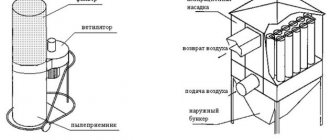
- When working, it is necessary to use a chip extractor or a special vacuum cleaner, for example, a cyclone type, to remove sawdust and dust from the sawing area, which can cause the following harm:
| To the Master | Respiratory and eye contact |
| Tool | Getting inside the instrument and:
|
| Process | Chips and sawdust getting between the workpiece and the table, resulting in poor fit and misalignment - the result is uneven processing. |
- When working, it is necessary to use pushers, since when working with small parts, it is possible that the master’s hands will get into the cutting zone, which will lead to injury.
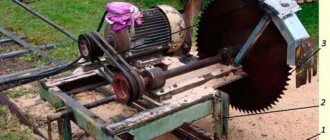
Making a knife shaft jointer
The main parts were made for the manufacture of the machine. For them, a rolled isosceles angle of 40·40 mm was used. You can use a 40·20 profile pipe with a 2 mm wall, then the parts will be assembled by welding (a jig or a slipway is required).
Components purchased:
- M12 studs, 120 mm long – 16 pcs.
- M12 nuts (32 pcs.) and washers – 16 pcs.
- Additional M10 bolts, Ø10 spring washers and M10 nuts – 52 sets.
- Electric motor power 3.5 kW (2880 rpm).
- Knife shaft 200 mm long with a set of knives and auxiliary fasteners.
- Corner 40·40 mm (6.8 m).
- Strip 4·40 mm (1.1 m).
- Pulley block for the motor and a pulley for the shaft.
- V-belt.
- Wires and starting fittings.
After preparing the parts, they are painted with a primer. You can start assembling.
Machine assembly
All parts of the future machine are laid out on the workbench. We have to assemble them and get a workable design at the finish line.
The upper and lower frames are assembled from the corners. Corners used here:
- 450 mm long (4 pcs.), Ø 10.5 mm holes (4 holes) drilled in them.
- 550 mm long (5 pcs.), they also have Ø 10.5 mm holes drilled in them (4 holes in 4 corners and 2 holes in one).
- 220 mm long (2 pcs.), 4 holes drilled in them. (Ø 10.5 mm), not 2 of them each for installing the knife shaft.
Corners for mounting the working roller are mounted on the upper frame. In addition to the holes for assembling the machine frame, Ø12.5 mm holes were drilled in the corners for mounting tables (feeder and receiver).
Before drilling, table plates were applied and markings were made.
Nuts are screwed onto the studs and washers are installed.
Knife roller, knives and wedge strips are located nearby. This shaft has three grooves for installing cutting tools. There is a strip nearby; an electric motor will be installed on it.
Table plates. There are three of them. Two are used for the jointing part, the remaining long element is used for the circular table.
For the planing part, two identical plates with a thickness of 10 mm are used. Their size is 220·300 mm. On one side, each has an oblique cut at an angle of 45⁰.
Spatial assembly. Vertical elements are being installed. Each unit is secured with two bolts.
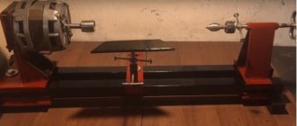
The result is a rigid spatial structure. In the future, it will be placed on an additional table to make it convenient to work with lumber.
The roller is mounted on pre-prepared supports.
Fastening is carried out with bolts through the bearing housing supports.
Pins are screwed into the table plates. They are threaded M12 (length 9.5 mm).
The technology for installing tables is quite simple. One of the nuts determines the installation height relative to the frame, the other fixes the given position. The washers prevent loosening.
All plates are installed on the machine. It looks like it's working.
Now it's time to place the knives. First, wedge strips are installed. They are inserted into the grooves from the end.
All that remains is to install the knives. In the future, they will have to be adjusted in height so that the wood is sampled to the same size.
The knives set at height are fixed with bolts. They are used to expand the groove; such an installation prevents the tool from flying out of the groove.
Place stripes at the bottom of the frame. An electric motor is mounted on them.
All that remains is to tighten the belt. The available pulley block allows the desired V-belt tension to be achieved.
The main assembly is complete. All that remains is to connect the wires and install the starting fittings. All that remains is to perform sea trials and adjust the position of the tables and knives.
Features of a DIY wood sanding machine
After cutting the wood, it must be sanded and only then proceed to the construction of buildings or the construction of other objects. There are several types of grinding machines:
Disk. The working surface is made in the form of a circle, onto which sandpaper or another sanding device is fixed on top. You can adjust the processing speed without changing the speed.
Device option with disk
Tape. A continuous strip of sandpaper is stretched between the two shafts. It’s not difficult to make belt sanding machines with your own hands, just prepare a detailed drawing and read the instructions
It is important that the emery in the working surface does not bend under the weight of the workpiece
Belt assembly process
Drum sanders for wood are common among woodworkers. Used for horizontal leveling of planes using the jointer method. The principle of operation is to attach the sandpaper to one or two drums, and under them there is a table with height adjustment. You can set the required calibration and make workpieces of the same thickness.
Home Drum Wood Sanding Machine
Calibrating and grinding machines for wood are universal machines that combine grinding and leveling of workpieces. Two types of equipment are used: disk and tape. You can make such a device yourself, with the right choice of drawings.
Calibrating and grinding equipment in production
To correctly assemble the appropriate version of the machine for grinding and processing wood, select the appropriate drawing and all components. Below are some examples of accessible and convenient equipment schemes:
A simple belt optionAnother equipment option with a belt principle of operationUniversal machine for working with woodHome disk machine in action
grinding machine
Let's take a closer look
Let's look at the example of a board that needs to be leveled on four sides. A simple groove-type cutter will be needed, ideally the wider, the fewer passes will be created for leveling. On the other hand, the narrower it is, the deeper the immersion into the wood will be, which makes it possible to remove more material in one go.
Note: If you need to remove a little wood, take a wide cutter, and if there is a lot, then use it already.
These methods can be combined
The workpiece is placed on a vertical surface. Now you need to make sure that the workpiece is motionless. This can be done using wood chips or thin pieces of wood. The main thing is that she is immobilized in a vertical position.
Afterwards we will need rails, instead of which we will use a profile pipe.
We will need: two rails of the same size, a device along which we plan to move the hand router. We will use the simplest cutter.
First, the rails are attached to the tabletop using a clamp. The rails must be pressed as tightly as possible.
The square pipe used as rails is made slightly smaller in size
Note: There must be a spacer between the rail and our material so that during operation the metal does not cling to the cutter.
Next you will need to fix the rails using clamps.
After everything is securely fixed, a certain device will be needed that will stand on the rails, along which the part will move up and down and select the tree.
Important: The workpiece is well secured so that there is no movement during milling. Let's start milling
If there is a need to plan a lot of wood, then it is better to do it in stages. If everything is prepared, we decide on the depth at which milling will take place. We now move on to direct milling, for which the cutter is driven along the surface of the workpiece
Let's start milling. If there is a need to plan a lot of wood, then it is better to do it in stages. If everything is prepared, we decide on the depth at which milling will take place. We now move on to direct milling, for which the cutter is driven along the surface of the workpiece.
Important: The work must be done very carefully so that the cutter does not touch the rails. This completes the jointer's work.
During cooking, the boundaries of the cut of wood fibers with a milling cutter will be visible. These areas are sanded to create a perfect surface.
Afterwards the router will work for the surface planer
First you need to thoroughly clean the countertop.
Now we take the leveled surface of our workpiece as a base. We don’t put anything under it now; the workpiece should lie on a flat horizontal surface. It only needs to be secured horizontally.
Now you can remove the required amount of wood. During the process, we measure and remove all excess from the reverse side.
Front movable table
The design of the front table is created in a movable form. It is represented by a combination of two parts that are fastened at an angle of 90 degrees. Strength can be significantly increased by creating side supports. The individual parts are fastened using self-tapping screws, but strength can be significantly increased by using wood glue.
The next step is to create two through holes 70mm apart. Fixation is carried out using two screws, for example, with wings. Due to this, the position of this element is adjusted.
Types of jointing equipment
Homemade equipment for long planing of wood can be made using different starting tools:
- Knife shafts - they are produced by separate factories as consumer goods. Three or four knives are installed on them, located at an angle of 90 or 120 ⁰. The working length of the shafts can range from 250 to 650 mm.
- Electric planers are a ready-made tool equipped with devices for setting, removing chips, turning on and off. For mounting on a table, there is a support frame that can easily be adapted for a small machine in a home workshop.
- Hand milling machines are power tools that provide high quality surface finishes. The productivity of the cutter is lower than that of the planing cutter. However, when processing wood, scuffing is practically eliminated. For hard wood, the use of this type of device is indispensable.
Some craftsmen create small jointing machines that have small overall dimensions and weight. They can be transported to the site. Already on site, the equipment is installed on trestles. Then the required amount of work is completed.
Industrial installations are quite heavy; they use cast iron or duralumin casting. For homemade designs, they use rolled metal or wood.
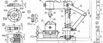
High-tech method for manufacturing a thickness planer
The author of this homemade thickness planer decided not to skimp on the technological equipment of the equipment being created and to electrify all processes as much as possible.
Read also: Soldering iron for soldering microcircuits with your own hands
There are 3 independent electric drives, which:
- drive the cutting drum,
- are broaching pressure rollers,
- adjust the position of the desktop.
Torque is transmitted to the drum using a V-belt drive, and in the two remaining options - a chain drive. Moreover, the uniformity of pressure on the rollers is regulated by interconnected spring-loaded intermediate sprockets, although in our opinion, such a system will still not allow us to avoid some temporary loosening of the chain at the moment the workpiece leaves the feed roller.
The tensioning of the drive chain for adjusting the height of the work table is carried out by two rigidly fixed sprockets.
Such an approach, obviously, can be justified if you have a flexible mini-production with a large number of equipment reconfiguration operations. Although here some schemes could be simplified. For example, like this:
Such a machine will not be cheap, and the abundance of rather complex components will require constant maintenance. But, apparently, this is exactly the case when the desire for self-realization was in the foreground, because for similar money it would be quite possible to find a used thickness planer and, having slightly repaired it, provide a solution to the same problems.
Additional Assembly Tips
The metal for the stove is cut with a grinder or jigsaw. To cut a groove, it is convenient to use an electric jigsaw, having previously drilled a hole for its file in the slab, or an electric drill with an appropriate attachment. The edges of the slot are processed with a file so as not to get injured by them later.
You can secure the metal base plate with flat head screws (so that they do not interfere with work) or by welding it. The first option is preferable because, if necessary, the electric plane is easy to disassemble.
Before installing the drum, it is recommended to check the sharpness of its knives. If it is bad, then it is better to sharpen the blades immediately, using, for example, a regular whetstone. It is necessary to constantly ensure that the cutting attachments are well secured without distortion.
The basis for making your own knives are steel plates or hacksaw blades for metal, sharpened at an angle of 30 degrees.
Hacksaw blade
The sequence of making an electric plane from a grinder with the working drum placed in a vertical position is demonstrated in the videos below. It also shows possible errors when assembling a homemade product.
Another option for creating a homemade electric planer from an old, non-working model is shown step by step in the video below.
Using the made power tool, you can process boards, beams and other workpieces. An electric planer assembled with your own hands must be used in compliance with safety requirements. The parts must be fed correctly to avoid getting your fingers caught in the drum.
There are many options for homemade electric planes. They have varying degrees of complexity, as well as different functionality. In this regard, the limitations are mainly related to the technical thinking of the inventors and the parts and materials available “at hand”. If necessary, the manufactured equipment can also be equipped with automation equipment.
Do-it-yourself thickness planer made from an electric planer
It is precisely this approach to solving most tasks for a surface planer that arise in a home workshop that we find most interesting.
First of all, this interest is based on minimal modifications to an existing tool to perform the work of expensive equipment with almost the same result.
By installing an electric planer on a platform with variable height, we get almost the same thickness planer. True, it is not the position of the work table that is regulated, but the position of the working tool in relation to the workpiece being processed, but this does not change the essence of the process. The role of the table here is played by a flat, powerful board with width limiters on the sides. They also serve as the mounting location for the main unit. But first, let's talk about him.
On the planer, we will replace the rear support plate with a homemade one made from OSB or plywood, with a thickness that ensures the same level as the front plate, which regulates the required gap (1 - 3 mm) for removing chips. Its width should correspond to the width of our improvised desktop.
On the sides of this plate, slats are screwed to attach the legs, the height of which is dictated solely by common sense. It is obvious that, based on the standard width of the plane knives of 82 mm, the thickness of the workpieces being processed should not be more than 100 mm, so the distance between the axes of the leg fastenings can be taken as 110 - 120 mm. Accordingly, their total length will range from 140 to 160 mm with a width of 35 mm and a thickness of at least 10 mm. The legs are fastened strictly at the same distance from the edge of the bar.
Installation of the assembled movable upper unit with an electric planer on the desktop is carried out locally, so that the fastening is strictly at the same level. This is done to ensure that its movement is parallel with respect to the base surface, which will ensure accurate processing of the workpiece.
The easiest way to set the height during work is by selecting slats of appropriate thickness, screwed onto the work table width limiters, or using other stands.
And the clamping of the working tool is ensured with spring ties or a harness, but for small workpieces this is not required at all. Also, in a given position, this parallel platform can be fixed with self-tapping screws.
Video of using a surface planer assembled by yourself:
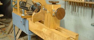
Step-by-step production of a planing machine and thickness planer based on it
The Interskol-110 electric planer is used as the initial sample. The working width of the workpiece being processed will be 110 mm.
To plan boards and bars, you need to set the plane with the soles up.
For the manufacture of the body, plywood 15 mm thick is used. Using circular equipment, blanks are cut out: sidewalls and supporting surface.
There are protection covers on the sides of the plane. To install the tool, they must be temporarily removed. Grooves will be cut into the sidewalls for installing an electric planer.
By applying the tool, determine its position relative to the sidewalls. This is the most crucial moment. How well the marking is done depends on the quality of future wooden parts.
When the base is determined, the position of the casing is marked. Its outline is outlined for further cutting.
A jigsaw is used to cut out a hole. You have to drill holes and install a file in them. For work, use plywood saws with fine teeth.
The casing is used locally. If the need arises, the hole is modified.
By analogy, markings were made for the second sidewall. A shaped hole is cut out for another casing and a pipe for connecting a vacuum cleaner.
The second casing is being tried on.
Two sidewalls allow you to fix the plane in a certain position. All that remains is to install a support platform, which will ensure the rigidity of the entire structure.
After assembly, a support for planing parts is obtained. It can be used for jointing blanks for furniture production.
Production performance check. The boards are jointed by moving the boards along the surfaces of the front and back areas. However, this design allows you to modify the equipment and turn it into a thickness planer. Then the craftsman will have the opportunity to grind the workpieces to a given thickness.
A small attachment, its movement occurs along the grooves. By setting the position of the attachment, you can set the desired planing size on the surface planer.
Reismus is ready. A machine was obtained from an electric planer, the cost of which is an order of magnitude higher.
Classification and capabilities
Thicknessers are divided according to different criteria. Despite the fact that surface planers have the same purpose, they can be different in design.
The machines differ according to the following criteria:
- By drive. Some homemade devices are manually operated, but the most common ones are electric. In domestic models, the electric drive operates at 220 volts, while in professional models it operates at 330 volts.
- By type of feed rollers. The machine can be equipped with one or two pairs of drive rollers. If one pair is installed, then very strong pressure of the workpiece to the shaft is required. The disadvantage of this scheme is the possibility of vibration during processing. Systems with two pairs of feed rollers are more practical and convenient. They are used in cases where it is necessary to process a large volume of workpieces.
- According to the number of shafts with knives. Their number affects the variety of profiles that can be processed simultaneously.
- In terms of functionality. Some machines can do not only rough processing of the product, but also subsequent fine grinding. In this way, various chips, dents and other defects that inevitably occur when jointing technologies are violated or when the craftsman makes mistakes are removed.
- According to technical characteristics. Typically, these devices are designed for power from one to forty kilowatts with a cartridge speed of up to 12 thousand revolutions per minute. Thicknessers can process workpieces from five to one hundred and sixty millimeters with a planing width of up to 1350 millimeters.
Thicknessers may also differ in the way they regulate gaps and in the design of the bearing assembly on the main drive.
Elements of a homemade tool
Electric planers were invented back in the middle of the last century and almost immediately gained popularity among builders.
They very quickly removed hand tools from the market due to high productivity.
Despite the absence of painstaking point processing, the plane allows you to perform the assigned tasks efficiently.
All modern models are quite different in appearance, but have common elements in the internal design. You can use an electric planer using one of two main methods:
- Use as a portable hand tool;
- In a stationary state, upside down (using reliable fixation on a workbench or table).
An electric planer that you can make yourself will have the same design elements as the factory models. Among them are:
- An electric motor that powers the tool;
- Protective cover (helps to save the operator’s hands from the sharp blades of the device);
- Start button;
- Knives mounted on a drum;
- Transmission mechanism (it helps transfer the rotational impulse from the shaft to the blades).
As a sole for an electric planer, it is allowed to use a flat slab (plywood, metal, boards), as well as a special workbench. The use of the second option is more preferable, since it does not require making legs for the machine. When using a stove, you will have to make a frame of sufficient height with your own hands. It must be suitable for the height of the planer operator so that it is comfortable to plane the wood.