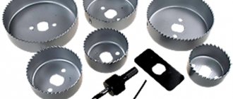
Today we will look at one of the types of processing of wooden products - wood planing. If you are going to build a house yourself, especially a frame house, then you will definitely need this.
Wood planing is a wood processing method that involves planing the plane of wood after sawing. The tool used for jointing is a jointer or plane (I will explain how they differ from each other a little later). The peculiarity of its work is to level the surface of the wooden workpiece, after which the working surface becomes smooth, even and without defects. Depending on the stages of jointing, different types of planes and jointers are used.
Planer and its purpose
When considering what a jointer is, we note that this tool is used to change the quality of the surface of wood. It largely determines how pleasant the final product will be. The jointer can look very different; the mechanical version is represented by a combination of three main elements:
In most cases, the body is made using wood, but there are also metal versions. A product with a wooden body is suitable for working with soft wood, while metal is designed to withstand heavy loads. When considering why a jointer is needed, we note the following points:
- It is used when it is necessary to align large fragments. In this case, the workpiece can have a large area and length.
- The installed cutters can be up to 8 cm wide, while the block is also characterized by quite large dimensions.
- The first use of the tool causes the formation of small chips, the second time causes the formation of long, uniform chips.
- There are a variety of types of tools on sale; the choice is made depending on the task at hand.
The manual version differs from the electric one, which has a complex design. It consists of the following:
- A thrust handle through which force is transmitted.
- Socket for connecting a vacuum cleaner. It is worth considering that at the time of work a large amount of chips may form. To ensure that it does not have a negative impact on the work being carried out, a special vacuum cleaner is connected, which immediately after the appearance of chips collects it.
- Control buttons allow you to set basic device parameters.
- Manual screw is found on almost all devices. It is required to change the planing depth.
- There is also a side stop, due to which the working width of the surface being treated is changed.
- Protective hinged cover that eliminates the possibility of damage.
- Sole. It comes into contact with the surface being treated and is often represented by aluminum.
- Many devices are characterized by having a built-in battery. In addition, there is also the possibility of connecting a cable.
Electrical equipment must be properly maintained. Long-term use requires sharpening.
How are repairs carried out on a ship?
Maintenance is what keeps any mechanical equipment or machinery running. Whether it's a small machine or a large structure, effective maintenance can help with longevity and a favorable outcome. On a ship, maintenance is what keeps the equipment up to date and running smoothly. In this article, we will learn how maintenance is carried out on a ship.
In the ship's engine room, where the maximum number of machines are located, engineers and crew carry out maintenance for safe and efficient operation. Every machine on board a ship requires maintenance, which must be performed at regular intervals.
In the old days, the number of crew and engineers on a ship was large, so maintenance was quick and easy. However, in the present scenario, the number of crew members and engineers on the ship has been drastically reduced.
Many ships only have 3-4 engineers on board, and even the time required to maintain the ship has been reduced. Maintenance requires manpower and time, which may not be available at all times since the number of crew members is less and the amount of equipment is more.
For this reason, it is important to plan equipment maintenance in advance so that it can be properly repaired and maintained. Typically, the second engineer must plan the ship's maintenance schedule.
Effective planning and adequate use of equipment are the keys to productive maintenance. In this article, we will look at the main types of maintenance procedures performed on a ship.
Types of Maintenance Procedures
1) Preventive or planned maintenance system
It is known as PMS or Planned Maintenance System. In this type of system, maintenance is performed according to the operating hours such as 4000 hours, 8000 hours, etc., or at calendar intervals such as 6 months, a year, etc. of the equipment. Maintenance is carried out regardless of the condition of the equipment . Parts must be replaced if scheduled, even if they can be used.
2) Maintenance or Troubleshooting
In this system, maintenance is carried out when equipment breaks down. This is the reason why it is known as hardware repair. This is not an appropriate or good method as situations may arise where the equipment is required in an emergency. The only advantage of this system is that the operation of the machine parts is used for its entire service life or until it breaks down. This system can be costly as some other parts may also be damaged when it breaks down.
3) Condition Maintenance system
In this system, equipment parts are checked regularly. Using sensors, etc., the condition of the equipment is checked regularly and appropriate maintenance is carried out. This system requires experience and knowledge, as misinterpretation can damage the equipment and lead to costly repairs that may be unacceptable to the company.
Tags: general recommendations Image Credits Planned maintenance Ship maintenance system
.Power supply: installation location and case selection - How to properly plan and select parts for an air-cooled PC, part 1 Power supply
: installation location and housing selection
Block based power supply
Many modern PC cases place the power supply under the motherboard. This installation option has many benefits, so we highly recommend a chassis configured this way. As you can see from the diagram, the fan draws cool air from floor level through the power supply's own intake, uses it to cool the active components inside the power supply, and forces it out the back of the device.
Advantages for bottom mounting :
• Continuously blows cool air from the floor to the outside of the case • Directly pushes out of the case • Lower fan speed • Cooler operation allows for more efficient power supply • Less thermal stress on components, longer life • Lower center of gravity • No overhead power cable
Flaws:
• The chassis must have a bottom opening • It must also have an air filter • Possible impact on acoustics depending on the floor material.
Despite the minor drawbacks, the above configuration is preferable to some of the other setup options that follow, and you should always look for a case that fits it. But this is also where you can go wrong:
Do not install the power supply with its opening facing up in the chassis. You should only go this route with passively cooled "quiet" power supplies to allow warm air to rise. Otherwise, you are fighting the forces of convection and possibly creating a situation where a screw or other loose part can become caught in the power supply.
Power supply at the top of the unit
Older PC cases built to the ATX specification place the power supply under the top of the case. Air is drawn in from inside the case and then expelled. This supposedly improves dissipation and prevents heat buildup. However, this also causes the power supply to absorb most of the heat generated by the graphics cards and processor. Consequently, you get inefficient operation from the power supply, making maximum power and efficiency nearly impossible to achieve at temperatures exceeding 40°C (as these are typically based on an operating environment of around 25°C.) The durability of the components inside the power supply will suffer too.
Advantages for top mounting:
• Helps with cooling in some systems • Shorter cable required for 12V connection
Flaws:
• Higher PSU temperature • Inefficient and loud operation • System ages faster
The perfect chassis...
… does not exist. However, large, well-designed towers like the Corsair Graphite 600T come very close. There is nothing that can restrict the airflow within the structure. Space, cable routing at the rear, and multiple fans and air filters combine to create a solution that fits what we consider ideal.
As much as possible, you should stick to cases that don't restrict airflow from bottom to top. If you want to include a particularly long graphics card in your configuration, use a chassis that is as deep as possible. Otherwise the card will split the air flow. Thick cables should always be at the back. Additionally, anything that rattles around will significantly disrupt the air flow.
,
Types of tools
The classification is very extensive and is associated with various properties. There are two main types:
- A hand jointer can be found in almost any workshop. Its peculiarity lies in the prostate of the device, as well as its low cost.
- Recently, an electric jointer has often been purchased. This is due to ease of operation, as well as fairly high efficiency in use. The only drawback is the fairly high cost.
The materials used in the manufacture of the main part may differ significantly. Wooden tools are more common, as they are simple and much cheaper. It is suitable for a home workshop. There are also metal structures designed to work in extremely difficult conditions.
The classification is carried out according to what the task is. Examples include the following devices:
- For working with wooden workpieces that have not been processed in any way before. This variety is called Sherhebel. In most cases, a metal is used that can withstand significant impact.
- If finished parts need to be glued together after processing, then tsinubel is used. This design option is characterized by the fact that the knife has serrations. After planing, small grooves appear on the surface. As practice shows, such a surface is best suited for gluing.
If the resulting products do not need to be glued together in the future, you can use a double or single jointer. The main types of carpentry tools include the following:
- The grinder is represented by a type of design, which is characterized by a shortened body and an increased rake angle, as well as a reduced slot for removing chips. The scope of application is to align the ends and remove various burrs.
- In some cases, a semi-joint is used. It is characterized by a reduced length, but the required width remains. Used when working with large parts.
- The folding belt is used for sampling and quartering. It has a design that has a removable sole. The tool differs from others in width and is a specific design option.
- Zenzubel has a double-sided knife made using high-quality steel. The width of this element is 33 mm.
Mini jointers are also available for sale. It is often used in domestic settings, as it is small in size and has sufficient performance. In addition, all devices can be divided into two main groups:
- Household is characterized by low cost, as well as reduced performance characteristics. It is widespread because it costs less.
- A professional jointer is used for work in industry. Its main qualities include increased productivity, as well as the ability to work for a long period.
The production of the instrument in question is carried out by a variety of companies. There is also an industrial jointer that can be used for a long period.
What is the difference between thicknesser and jointer machines?
Planing machines are designed to level out uneven surfaces of boards and timber. Planing perfectly removes traces of deep cuts and curvature, which was caused by warping that appeared as a result of drying the wood. After processing on such machines, the workpiece becomes suitable for subsequent work. It acquires a perfectly flat plane of sides with parallel edges.
On the one hand, the design of planer and planer machines is almost identical. They are designed for cutting (planing) the edge of a workpiece in order to level and create a smooth surface. However, the latter differs in that it has an upper clamping edge (or knives) that makes it possible to obtain a cutting line parallel to the opposite one.
Design of a jointer-planing machine Source jettools.ru
Thus, based on the design features of the equipment, the comparative characteristics of the machines can be completed as follows. The planer is designed for planing; it can also be used for leveling individual sections. For example, it makes it easy to get boards with different end thicknesses.
The thicknesser machine processes only pre-prepared boards or timber. You can plan on it, as you can on a regular jointer, but to do this you will have to lift the upper pressure shield (if this is possible based on the design features of a particular machine). In fact, its purpose is to process parallel sides. Therefore, if the board is crooked, then after processing it will turn out to be the same, only with the same distance along its entire length.
How to make a diagonal cut on a surface planer Source pinimg.com
Electric
Today, a stationary jointer can be manufactured in an electric version. Professional devices are characterized by the following features:
- Quite a large mass and clamping force.
- During operation, high precision can be achieved.
- Increased labor productivity.
- Often the design provides the ability to quickly change knives.
Read also: What is circuit inductance?
An electric jointer is used in industry and everyday life; the product is characterized by high performance characteristics. The only drawback in most cases is the high cost, as well as significant energy consumption.
Planer or planer
A fairly common question is what is the difference between a planer and a jointer. Both options allow material to be removed from the surface. The difference is this:
- The plane is intended for primary work. As a rule, the layer of material for which the equipment is configured is removed from the surface. Planing is carried out to remove knots and bumps. The design is represented by a combination of a knife and a block; in some cases, two cutting elements are installed.
- The jointer is considered a type of the first tool; it is a long version of the body, due to which the device is pressed with great force onto the surface being processed. In this case, 2 blades are also installed, which provide a finishing jointer.
Both options are found in the standard kit of a professional who processes wood.
WOOD PROCESSING ON FOUR-SIDED PLANING AND MOULDING MACHINES
A four-sided planer is used for simultaneous planing of material on all four sides in one pass. In this case, the edges, and in narrow materials also the face, are often planed according to a shaped profile, i.e., in a quarter, tongue, groove, in the form of a groove, in the form of the front side of platbands, baseboards, cornices. The four-sided machine essentially combines a jointer, surface planer and milling machine. The machine has two horizontal knife shafts - lower and upper - with straight knives and two vertical spindles. Knife heads, cutters or chucks with shaped knives are mounted on the spindles. The lower knife shaft and vertical spindles are built into the frame and into the work plate. The upper knife shaft can be moved vertically to set the desired planing thickness. The spindles can move in vertical and horizontal directions according to the width and thickness of the material being processed. The front part of the machine's work plate is movable. Like a jointer, it can be moved up and down to adjust the thickness of the chips removed. The material is fed using two pairs of drive rollers, of which the upper rollers are corrugated and massive. The machine is equipped with several clamps - top and side. Feed rollers and clamps press on the material either by their own weight or by means of weighted levers or springs. Machines with five knife shafts are widely used. The fifth knife shaft, the last one along the material flow, is located at the bottom and is used for profile planing of the material from the bottom side. The working shafts of the machine operate from one common electric motor through a counter drive or from individual electric motors. The total required power of the machine is from 30 to 100 kW. The control of the machine with individual motors is push-button. The speed of the knife shafts is 5000-6000 per minute. In machines of the latest designs, knife shafts are made up to 9000 rpm. The four-sided machine can be easily adapted for planing material on only three sides: to do this, just turn off the lower knife shaft. The design of the molding machine, used for the production of layouts, cornices, and posts, is close to the four-sided one in design. The molding machine is smaller in size than the four-sided one. On a four-sided planer, the material, in most cases a board, is fed along guides into the feed rollers and is pushed onto the lower cutter shaft. Here the bottom face is cut off, as on a jointer. A massive roller clamp presses against the knife shaft onto the board from above. With further advancement, the board passes through two vertical spindles with flat or shaped knives or cutters mounted on them. With these tools, both edges of the board are processed according to a given profile. In front of the spindles, in close proximity to the cutting edges of the knives and cutters, there are two guides. In addition to their main purpose, they are used to support fibers when planing edges and as chip breakers. Both guides can be moved horizontally along and across the table and set depending on the width of the boards being processed and the radius of rotation of the cutting tool on the vertical spindles. Behind the vertical spindles there is an upper knife shaft that planes the upper surface of the board. In the output part of the machine, the board slides onto the fifth knife shaft with shaped knives, if the lower surface is processed for a profile. The boards must be fed into the machine without breaks - end to end. This is very important, since each new insertion of a board under a heavy corrugated shaft requires significant effort and additional time. Of the four-sided planing machines of previous production, the most widely used is the SKP 30-2 machine in Yaroslavl. This machine has 5 knife shafts; the maximum planing width on it is 300 mm, planing height is up to 175 mm; feed speed - from 9.5 to 48 m/min. The machine is electrified, its total power is 20.5 kW; weight 5500 kg. The part, planed on all four sides, is trimmed to size on a cross-cutting machine. The next stage of machining is giving the parts their final shape. At this stage, the tenons are filed down, the sockets and eyes are selected, the quarters, tongues and grooves are selected, and the final processing of curved surfaces is performed. Finally, the parts are polished. Completely finished parts are transferred to the assembly. There are many different machines available to give parts their final shape. Large enterprises have several types of tenoning and drilling machines, edge jointing machines, winnowing ribs and round-stick machines for sealing knots. The narrower the specialization of the machines, the less the loss of working time for their readjustment. With a smaller production volume, the number of types of machines is reduced, and machines are adapted to perform various operations. At the same time, as a rule, manual work increases. Continuation of the book...
Difference from surface planer
Also, many consider what is the difference from a surface planer. When considering a thicknesser and a jointer, it should be borne in mind that the first option is intended for drawing parallel lines on the surface. Both options can process wood; among the features, the following points should be taken into account:
- Flat surfaces can be obtained with a thicknesser, but the equipment is designed for finishing.
- Both tools work exclusively in conjunction. The jointer is intended for preparation, second final processing.
In general, we can say that there are quite a lot of differences. In this case, the structural elements differ insignificantly, but the thicknesser allows you to reduce the degree of roughness of the surface layer.
How to joint boards correctly
The wood cutting machine used is characterized by its specific properties. Jointing is a process of processing the surface of wood of varying densities. The recommendations are as follows:
- Take the handle with your left hand, and the block with your right.
- The tool is guided along the fibers.
- As the product is ready, the chips become long and even throughout their thickness.
When working, do not handle the blade; you should wear protective clothing while working. At the time of work, the boards must be securely fastened.
Planer-thicknesser machine
There is also a planer-thicknesser machine, which provides high-quality processing. The advantage of the device is its increased functionality.
In most cases, the device is installed in industry. This is due to the fact that it is quite expensive and can significantly increase labor productivity.
High-quality processing is guaranteed, but the equipment must be used correctly.
For what purposes is the equipment used?
It is worth buying a planer-thicknesser machine if the production process requires the following tasks:
- reducing the thickness of the workpiece by removing wood layers in the required quantity;
- removal of various types of defects on the surface of the workpiece (irregularities, warping, deformation);
- eliminating wood roughness;
- creating on parts the edges necessary for the final product.
Advantages of devices
The main advantage of a planer-thicknesser for wood is the combination of the functions of two devices. Such equipment significantly saves the cost and time of the work process. It can be used both in large-scale production and for domestic needs. The resulting material is of high quality and meets the exact parameters of the required thickness.
Operating principle
In the design of these working machines, the main element is a powerful electric motor equipped with a temperature sensor that protects it from overheating by turning off the system when the temperature mark reaches the critical point. Other components are a bed and a working surface, consisting of a feeding and receiving part, a knife shaft with a number of knives that varies for individual equipment models, and a ruler that allows you to adjust the height of the knife. Material feeding can be either manual or automated. The product can be equipped with stops designed to install parts at the required angle of inclination.
The actual working process begins with feeding pre-sawn material onto the work table and moving it under the knife shaft. Thus, the wood is cut to the required thickness and at the same time its surface is polished to eliminate defects.
It should be noted that there are different types of planer-thicknesser machines. The price depends on the type (single-, double- or multi-sided depending on the method of processing workpieces), power, size, type of installation (stationary, mobile).
Do you need a high-quality planer-thicknesser machine? You can buy this equipment at a profit in Moscow from our company, which has been supplying woodworking equipment to the consumer market for a long time. We offer jointing and thicknessing machines for wood, the price of which is competitive. The advantage of purchasing from us is also the availability of documents confirming the high quality of the products and their compliance with international standards. In addition, you can order delivery from us to any point in Russia, carried out within a strictly specified time frame.
Features of operation and device
The equipment in question is characterized by certain application features. Among the features we note the following:
- The bottom surface must be level. This can be achieved by pre-jointing.
- Simultaneous processing is only possible when using a machine that has the appropriate properties.
- The machine is ideal for working with previously unprepared workpieces.
- The device is designed as a combination of several parts, all of which are responsible for specific functions.
In general, we can say that such a machine is characterized by high functionality. The design of a jointer of this type may differ significantly.
Recommendations when choosing equipment
When choosing which machine to choose is a very common question, you need to pay attention to several main points. They are as follows:
- Number of knives on the working part.
- Power of the installed engine.
- Dimensions and weight of equipment.
- The speed of movement of the workpiece at the time of processing.
All parameters should be taken into account when considering the most suitable design option.
Types of machines
There are quite a large number of different machines that can be used for working with wood. The asynchronous motor is protected by a special casing. Equipment with simultaneous planing and thicknessing functions has several advantages:
- The switch is made in the form of a rotary block.
- In most cases, the frame is made with powder paint, which significantly increases the protection of the surface from environmental influences.
- Submission of material can be carried out at any time.
- Provides protection from environmental influences.
- Some models come with two blades.
In most cases, classification is carried out according to engine power, functionality and some other characteristics. In addition, the popularity of the brand is important.
Sharpening jointer knives
Do not forget that knives should be sharpened periodically. Even when using high-quality steel, there is a possibility of damage to the cutting edge. The features of the process include the following:
- Requires special equipment.
- You need to maintain a certain angle.
- Even minor defects can cause a serious reduction in efficiency.
You can sharpen the jointer knives yourself, but this requires certain equipment.
Safety precautions when using a jointer
Considering the design, it allows processing in a wide variety of conditions. The main recommendations are as follows:
- Protective clothing and goggles must be used.
- Do not touch the blades or place your hands in the cutting area.
- The workpiece must be securely fastened.
In general, we can say that the jointer is a common tool that is found in almost every workshop today. You can choose the right one solely based on what work will be done in the future.
If you find an error, please select a piece of text and press Ctrl+Enter.
Wood processing has become firmly established in the production cycle of producing high-quality raw materials. Leveling the surface is done using a manual or electric plane, jointer, thicknesser. A stationary jointer and industrial planer-thicknesser machines are used.
Machine MD 250/85-Р120 —Kiev—
Hello everyone, my name is Svetlana and in this article we will look at a machine with a surface planer MD 250/85-P120, which is a more advanced version of the MD 250/85 machine with a large set of functions and capabilities.
Let us immediately note that this model is not as popular as the MD 250/85 model because the price is three times higher. The main consumers of this equipment are home craftsmen who are not always willing to pay a lot of money for equipment for utility work.
So, the MD 250/85-P120 machine is intended for processing wood at home.
Electric hand tool
For simple operations on processing short boards, hand tools with an electric drive are used. To trim the surface, a lot of force is required, so an electric motor was added and the design was slightly improved. Because of this innovation, its performance characteristics have improved:
- the mass has become larger, the pressing force has increased;
- processing has become more accurate;
- work has accelerated;
- Replacement nozzles have appeared in the kit sold.
Read also: How to replace a wood router
Planer, jointer or planer
All three tools level the surface of the wood, and their difference lies in the different quality of the resulting surface and the principle of stripping technology:
- The plane makes the first pass when preparing the surface, removing the top to the thickness of the working blade setting. Planing actively combats bumps, knots, and other irregularities. A plane as a working tool contains a knife and a block. There may be two knives in the design, then they are located one behind the other and the second one removes thinner chips, making the surface even, but the final turning is done with another tool.
- A jointer is essentially a type of planer; it has a more advanced structure. The body of the jointer is longer and heavier, this gives a tighter pressure to the processing area. Blades (2 pcs.) are configured for finishing penetration.
- A jointer is often confused with a surface planer, but the purposes of these tools are different. The jointer levels the wood, and the thicknesser is needed to transfer parallel features to the part. An electrically powered manual thicknesser lays out parallel lines to the specified size.
In the operation of professional machine tools, a distinction is made between the operation of a surface planer and a jointer:
- The jointer removes a certain layer, imparts a flatness to the surface, the end on the jointing equipment is processed in a perpendicular direction to the main plane;
- To make the planes perfectly parallel, a thicknesser is used, but its work is possible only after preliminary alignment.
Proper Use of a Portable Electric Planer
Jointing refers to the processing of wooden elements using any type of jointer. The portable tool can be fixed permanently for ease of processing. Procedure:
- the tool is secured to the workbench; when moving the board, a stop must be provided for it;
- the board is placed on the blade of the device against the stop after turning on the power of the tool;
- To obtain the required surface quality, the board is passed along the blade several times.
To control the thickness of the cut layer, a line is drawn with chalk on the workpiece. The layer above it should disappear smoothly, and the line itself should be removed if an even workpiece is obtained. To work with the edge, the board is turned to the blade with the corresponding side, then all actions are repeated in the same sequence.
Working with a jointer mounted on a work table is not difficult, but requires compliance with safety precautions:
- hands should not be in the blade working area;
- the work is performed using special protective clothing;
- To avoid holding the board with your hands and putting them in danger, use clamp-type holders.
To protect the worker from premature switching on of the tool, it is equipped with a protective tool control system. There are two power buttons on the case; power is supplied only when they are pressed simultaneously.
External structure of the hull
There is a socket on it for connecting the vacuum cleaner pipe and making it easier to remove chips; most often, models are equipped with such an entrance on the right. A handle for support during operation and control buttons are installed on the body. There is a manual screw to adjust the planing depth and layer thickness. To change the width of the processed strip, a stop is provided on the side .
The tool has a protective casing that can be folded down when needed. The lower sole of the unit is made of thick aluminum sheet. On the case there is a connector for connecting a battery or batteries with a voltage of 18 V. The kit includes a working cable 2 meters long with a plug for a household network.
PLANING ON A JOINTING MACHINE
The device of a jointing machine
.
On a jointing machine, straight parts are planed from two adjacent sides - under the ruler and into the corner. The main parts of a jointing machine are a bed, two cast iron plates forming a work table, a knife shaft (knife head), planing knives, and a drive. Each worktable plate can be raised or lowered along inclined guides using a screw. A knife shaft is placed between the plates; it is located so that the cutting edges of the knives mounted on it are at the same level with the back plate (relative to the machine operator). The front plate of the mouth is poured below the rear plate by 1.5-2 mm, i.e., to the thickness of the chips being removed. At the ends of the plates facing the knife shaft, steel linings - jaws - are attached flush with the surface of the plates. Their purpose is to protect the ends of the slabs from abrasion and chipping, to reduce the gap between the knives and the slabs and to support the fibers when cutting chips. There is a guide ruler installed on the desktop that can be moved along the width of the table. A safety shield or safety curtain is installed above the knife shaft, which during operation are moved aside by the workpiece, and after the part has passed, under the action of a spring, they again close the entire shaft with knives. The jointer is powered by an electric motor; transmission is belt or direct. The industry produces for the jointer a conveyor mechanism for feeding material and an apparatus for jointing and straightening knives at the installation site. The conveyor feed mechanism can be installed with its existing columns on the table of any jointing machine; To do this, you just need to drill holes in the table for the bolts attaching the speakers. On jointing machines with a conveyor feed, you can plan only the wide side of the part - the face. Joining of edges, smooth or with the selection of tongues and grooves, is carried out on an edge jointer or automatic tongue-and-groove double-sided machine with a conveyor feed. The conveyor of these machines is placed on edges; on both sides there are boxes with spring pressure shafts. These machines are highly productive and provide good quality work. The apparatus for jointing and straightening planing knives on site is produced both together with the machine and separately. In the first case it is folding, in the second it is attached. This is how you use the device. The working (sharpening) part of the apparatus is brought into light contact with the blade of one knife on the knife shaft and secured in this position. After this, the device is turned on and moved along the guide along the entire length of the knife, aligning the blade at a certain distance from the center of the shaft and at the same time straightening the blade. At the end of the operation, by turning the knife shaft, a second knife is brought under the working part of the apparatus and jointing and straightening are repeated. This is how the blades of all knives fixed in the knife shaft are processed one after another. Currently produced jointing machines are distinguished by a high number of revolutions of the working shaft, an increased number of knives, conveyor feeding, and high power. Working on a jointer
. When planing on a planer, the part is placed on the work table, if possible at right angles to the knife shaft. With the left hand, the material is pressed tightly to the table near the knives, with the right hand, further from the knives, and in this position the material is fed onto the knives. When the front end of the part passes behind the knives, press the part with your left hand to the surface of the back plate near the knife shaft itself. As the part moves, the hands are rearranged, but in such a way that the pressure on the part with the left hand occurs as close as possible to the knives. You cannot move both hands at the same time. The pressure on the part should be more or less the same, and the feed should be smooth, at a uniform speed. The warped part is laid with the concave side down, since on the convex side it will not have stability, and the planed surface will be uneven (not under the ruler). Heavily warped parts, in which the deflection arrow is greater than the processing allowance, cannot be planed. Such parts should be set aside for additional cutting into narrower or shorter parts, depending on the nature of the warping. Each part must be quickly but carefully inspected before planing. Parts with defects that are unacceptable according to technical conditions, especially with knots in places where tenons and eyes are made and holes are hollowed out, must be set aside for additional cutting. If this is not done, the part will still be rejected during assembly, and the wood, labor and time spent on such a part will be wasted. When planing the second adjacent side, the part is pressed against the table and against the guide ruler. Planing should be done layer by layer to avoid excessive tearing of the fibers. The best chip thickness is 1.5-2 mm. With such a thickness of the removed layer, the part is usually cut out in two passes, regardless of its size. When processing pine parts, the work table of the machine must be wiped with a rag moistened with kerosene, since the resin adhering to the table makes it difficult to move the parts. The parts to be processed must be positioned so that the machine operator does not have to make unnecessary movements. When feeding by hand, narrow parts are planed several at a time. Take as many parts as your hand can grasp. In this case, you need to be careful not to touch the surface of the table with your fingers in order to protect them from contact with the knives. Jointing the edges of thin plots is usually done in batches. When working on a machine with a conveyor, parts must be fed end to end. When planing narrow material, as one or another section of the knives becomes dull, the guide ruler is moved across the width of the work table to another section. This allows you to change knives less frequently due to dullness and thereby save working time. The main possible defect in planing on a jointing machine is the non-straightness of the planed surface. It occurs as a result of weak or uneven pressure on the workpiece. When setting up the machine for operation, you need to leave the smallest gaps between the knife shaft and the steel jaws, necessary only for the unhindered rotation of the knives. This is dictated primarily by safety considerations, since you can get your fingers into large gaps if you are careless. In addition, larger gaps result in less clean planing. The protective shield or curtain over the blade shaft must always be in good working order. Planing of short parts must be done using a block.
Stationary electric jointer
Such stationary units are much more expensive than portable options, but their functionality is much wider. Operations that can be performed on a stationary jointer:
- the beam is planed quite long, the cross section is processed;
- the ends are made at any angle, a selection is made in the body of the board of figured elements or through gutters (such operations are not done with a hand-held electric tool);
- the array is turned with a width of 600 mm, the length is allowed up to 3 m, and the thickness of the incoming part should not be less than 13-15 mm;
- Hard and durable wood is allowed for processing, which cannot be processed with portable tools of low power.
On jointing machines, the blade shaft speed is up to 6 thousand per minute, high productivity is obtained due to the high power of the equipment (6 kW). Other characteristics and parameters of the jointer look like this:
- several working knives, their diameters are different;
- there is a permanently installed guide rail in the design, called a ruler;
- the work table-bed is height adjustable;
- protective covers can be folded back if necessary;
- the knife shaft moves along the axis and fixes the cutting depth.
Principle of operation
The knife shaft of a stationary machine is located perpendicular to the axis of the bed in radial rolling bearings, which leads to compensation of all possible shifts of the part during operation and uniform distribution of the working forces of the two blades . The work table consists of two parts, where the back part is made stationary and stands on the shaft axis, and the front part rises or falls to the height of the layer being planed.
The part is fed manually or automatically, and in the memory of such a machine with software there are several options for processing different categories of wood. Some models provide planing of two surfaces at the same time.
To make adjustments in operating mode, lower the table, place the required number of knives on the shaft and adjust their parallel arrangement using the indicator. After this, all parts are secured and the feed mechanism is turned on. Before operation, the machine is checked at idle speed .
The design of a jointer, stationary or manual, is fundamentally the same. An electric motor rotates a knife drum with several removable blades through a reduction gearbox. As the tool head rotates, a vertical feed is imparted. Included with the equipment are several types of blades for planing hard and soft wood, their number ranges from 1 to 3.
How to set up and sharpen a plane
Planing with a hand plane
Sharpening plane blades includes proper sharpening of the plane knives without creating a distortion of the blades and their correct installation.
The quality of using a plane directly depends on the correct sharpening of the plane blade . It is sharpened on an emery stone, moving the bevel of the knife along the plane of the stone. The bevel of the knife must lie on the stone with its entire area. The angle of the blade when sharpening must be maintained throughout the entire sharpening process. Otherwise, the chamfer plane will be uneven, which will spoil the cutting quality of the plane knife.
The chamfer of the knife should be moved along the emery stone until a burr appears along the entire length of the knife blade. It is easy to identify by touch with your fingers. Then we place the blade flat on the block with its front edge and move it along the sandpaper in circular or straight movements with slight pressure. As a result, the burr disappears from the front edge and appears on the chamfer. We turn the knife over again and remove the burr from the chamfer. We repeat these techniques until, after several manipulations, we achieve the complete disappearance of the burr both on the front edge and on the chamfer of the knife blade. But this is only the initial stage of sharpening the knife and setting up the plane.
After the burr disappears, we edit the cutting part on the whetstone, having first moistened the whetstone in water. Using light circular movements, we move first along the front edge and then along the chamfer of the blade. This will be the next step in sharpening the knife.
Sharpening a hand plane knife
When sharpening a knife blade, you should periodically check with a square to see if the blade is warped. The cause of this distortion may be the incorrect position of the knife during sharpening or a manufacturing defect. In both cases, the defect must be eliminated. To do this, grind off the highest part first, then the rest.
Planer device
When grinding, the knife should be tilted in the opposite direction to the side on which the blade is skewed . At the moment of alignment, move clearly perpendicular to the cutting part.
When sharpening a plane knife, you need to take one point into account. It is necessary to round both ends of the cutting part. If this is not done, then during jointing of wood the sharp corners of the knife will leave grooves on the planed surface of the workpiece, which will subsequently be difficult to eliminate. But this is the final stage of sharpening the plane knife.
Checking blade straightness
Installing the Planer Blade
After properly sharpening the plane knife, it must be correctly installed in the plane block. The main thing is to correctly set the release of the cutting part. The knife is inserted into the opening of the block and slowly clamped with screws in a metal block or a wedge in a wooden block.
We raise the plane at eye level with the sole of the plane up and make sure that the cutting part of the knife protrudes clearly parallel to the sole . The planing layer of wood depends on the release of the cutting part above the sole.
Excessive release of the blade will penetrate deeply into the wood, at the moment of planing the wood and remove quite thick chips, constantly clogging in the opening between the block and the knife.
Planer setup diagram
If the release of the cutting part is too small, either the blade will remove too thin a layer, or jointing will be impossible at all.
After adjusting the knife , it is worth fixing it by tightening it with clamping screws or fixing the wedge with a gentle blow of a hammer.
Planer-thicknesser machine
It is a combined unit that organically combines the functions of a thickness planer and a jointer. Its advantage lies in this functional combination.
Read also: Diagram of a thyristor welding machine
After the initial cutting and pre-processing of the boards, they are sent for surface thicknessing and jointing. The task of the paired equipment is to eliminate all irregularities. The machine consists of a work table attached to a frame. The workpiece is fed to the bed, and the work table is intended for receiving; between them there is a knife shaft with blades.
The workpiece is fed to the bed and, through automatic or manual feeding, moves towards the work table. At the same time, it interacts with the blades of the knives, which rotate and clean the plane of the part. The difference between this type of machine and jointing equipment is the ability to plan to a given depth. The knife of thicknessing equipment is located on top, but some models provide for the location of knives on the surface of the work table and under it. To determine the height of the blade, use a ruler located on the body.
A planer and at the same time a thicknessing machine performs two operations simultaneously, so its use is justified in large-scale industrial production. It can be used in the construction of high-rise buildings. High-quality processing is guaranteed, and incoming primary lumber can be corrected on site without any problems.
Features of operation and device
If you only use a jointer or surface planer, you will not be able to achieve a properly processed surface:
- the lower surface for processing on thicknessing equipment must be leveled, which can be achieved by preliminary jointing;
- if necessary, you can process two surfaces - one by jointing, the other finally - by thicknesser;
- Thickening and jointing simultaneous processing is possible only on a machine with these combined functions;
- The planer-planing machine copes well with workpieces that have undergone not very high-quality initial processing;
- The Federal Reserve System consists of two parts, each of which is responsible for specific functions.
Recommendations when choosing equipment
The woodworking market offers a large assortment of FRS. When choosing a worthy unit, pay attention to the following parameters and characteristics:
- number of knives on the working shaft;
- dimensions and weight of the machine included;
- engine power;
- the speed of movement of the workpiece during processing.
Types of machines
The machines are a single system of planing and thicknessing. The powerful asynchronous motor is protected by a belt drive from increased overloads and operates with reduced noise emissions.
If during operation there is a failure in the electrical power supply, then spontaneous restart is impossible due to the use of a magnetic starter in the design. To reduce friction, the surface of the bed and work table is made of polished cast iron. For ease of operation, the receiving table and the serving table are made quite long. Switching from planing to thicknesser and back occurs quickly; for each mode, the nozzle has two positions. The machine operates without vibration.
Machines with simultaneous planing and thicknessing have undeniable advantages and improvements:
- the switch is made in the form of a rotary block;
- Powder coating is used to cover the frame;
- the durability of the frame and its protection against corrosion is due to the material used - cast iron;
- the feed can be turned off at any time;
- human protection from wood dust is provided;
- For ease of height adjustment, a convenient handle is provided;
- Some models use knives with double blades.
Jointing and thicknessing without errors
Planer and planer machines work in a similar way, removing a layer of material from the face or edge of a board, so the purpose of these machines is often confused. Both serve to level the surfaces of lumber and give it a rectangular cross-section, but each is used in a specific way and performs different operations. A planer-jointer can make one face of a board flat and the adjacent edge perpendicular to the face, but it is not able to give this board the same thickness along its entire length - this is the work of a thicknesser. Thus, planer-jointer and thicknesser machines work in conjunction. The production of flat workpieces of the correct shape begins on a planer-jointer, so we will first consider it.
Jointing: a basic step in achieving success
How does a jointer work?
As can be seen from the diagram of the jointing machine (Fig. 1), the front and rear tables are separated by a cylindrical knife shaft. The front table is installed just below the top point of the circle described by the knives, the back table is on the same level with it.
When feeding the workpiece onto the knife shaft, the knives remove that part of the material that is below the plane of the back table. The treated smooth surface then moves along the back table. With each subsequent pass, another portion of wood is removed until the entire processed side of the board is flat.
Squeeze the plastic first
Before jointing, look along the edge of the board to check for buckling or warping (Figure 2) and to determine the direction of the grain. For best results, plane a warped board so that the convex side faces up (in other words, the board rests on its edges) and the grain points down and back (Figure 1). If the fibers point upward, the moving knives will tear the fibers away, causing small pieces of the workpiece to break off (called pullouts). To trim the face of the board, set the front table to a cutting depth of no more than 1.6 mm. Place the board on the front table in front of the cutter shaft. Using pushers, push the board forward. The downward pressure should only ensure that the board contacts the front table, but nothing more (photo A). Excessive clamping force can straighten longitudinal or transverse warping, and after the clamp is released, the board will return to its previous shape.
Press the board with pushers. The main effort should be directed at moving the board forward, and not at pressing it against the table.
Apply only slight force to ensure that the finished part of the board remains in contact with the back table. Use both hands to feed the workpiece forward.
When about 15cm of the board is above the cutter shaft, move your left hand (and pressure) to the end of the board on the back table (photo B). About halfway through the pass, move your right hand to the machined part of the workpiece and continue to push it forward evenly until the pass is completed (Photo C).
Move your hands as needed to press the finished portion of the board against the back table. Pass the entire board over the blade shaft.
Draw a sinuous line with chalk up and down the board. It will help you track the progress of your work. When the line disappears, the board can be considered flat.
There is no need to remove more material than necessary. To control the result, draw a wavy line on the board with chalk. If the board has significant transverse or longitudinal warping, some material will be removed on the first pass (photo D ). With each subsequent pass, the board will become flatter and the treated surface wider. If the chalk line disappears, the board has become flat.
Having leveled the fall of the board, mark it as shown in the “Tip of the Master”.
Master's advice
During the initial processing of materials, it can be difficult to remember which face of the board has already been processed and which edge is perpendicular to this face. Therefore, after the last pass, mark the surface you just finished. Traditionally, furniture makers put a squiggle on the surface, and the edge perpendicular to it is marked with a tick, the point of which is directed towards the surface.
Then finish the edge
Apply force in two directions, pressing the board against the longitudinal fence and feeding it forward onto the cutter shaft. When working with boards less than 100 mm wide, use pushers.
After one edge of the board is leveled, it will not be difficult to trim the edge at a right angle to the edge. Perform the same steps as when jointing a board, with just one addition: when feeding the board, as described above, press it tightly against the longitudinal (parallel) stop (photo E). If possible, to prevent tearing and chipping, orient the workpiece so that the wood fibers are directed down and away from the direction of rotation of the cutter shaft (Fig. 1).
Mark the finished edge as shown in the Craftsman's Tip. Now that one of the faces of the board has become flat, and one of the edges has become perpendicular to this face, it is time to move on to the thickness planer.
Thickening: make blanks of any thickness
How does a thickness planer work?
Unlike a planer and planer, the knife shaft of a thickness planer is located above the workpiece parallel to the table (Fig. 3). By lowering the knife shaft after each pass, we reduce the thickness of the workpiece and make it uniform along its entire length.
When working with a thickness planer, there is no need to control the workpiece during the pass. To do this, feed rollers are used, located on either side of the knife shaft, which press the workpiece and at the same time pull it through the machine. That is why it is so important to first remove one edge of the workpiece. In the absence of a plane, thanks to which the board could be based on the machine table, the feed rollers will simply press the board against the tables, and the knife shaft will plane its top surface. As soon as the board comes out of the lathe, any existing longitudinal, transverse warping or winging will reappear.
The truth about thicknessing
When feeding a workpiece into a thicknessing machine, you also need to take into account the direction of the fibers. However, it should be remembered that this machine processes the board from above, so the rules here are reversed. To reduce tearouts, orient the board so that the grain runs up and back (Figure 3).
Removing a layer of material no thicker than 0.8 mm in one pass also reduces the risk of tearouts. If the machine has two feed speeds, make the final passes at a lower speed - this will give a cleaner surface. For the same reason, before the last pass, it is recommended to set the cutting depth to no more than 0.4 mm.
Before passing a short board through a planer, temporarily glue two bars to it. In this case, the step will appear on the bars, and not on the workpiece.
A small depth of cut also reduces the size of the step formed at the ends of the workpiece. To further reduce the size of a step or eliminate it entirely, support long boards with your hands or supports at the beginning and end of the pass so they lie flat on the machine tables. When processing short boards, use auxiliary bars glued to the sides, which are removed after thicknessing (photo F ).
If to sharpen a board to the required thickness it is necessary to remove more than 3 mm of material, then after processing the top face, turn the board over and process the previously jointed face. Work the board alternately on both sides until the final thickness is achieved. Removing approximately the same amount of material from each face makes the workpiece more stable, reducing the risk of warping.
Still having problems? May require adjustment
If you have followed all the directions exactly and are still not seeing good results, the machine is likely out of alignment. Even the most advanced woodworking technology in the world cannot fix this. If you suspect that something is wrong with the machines, read the articles on setting up equipment published in our magazine.
Tips for using a jointer
- To reduce the amount of waste and increase the yield of material, cut the boards to length and width before jointing, leaving an allowance for further processing. Short and narrow workpieces have less deflection and can be processed in fewer passes.
- For a smoother surface with fewer tears, remove a maximum of 0.8mm of material in one pass. Reducing the feed speed also produces a cleaner surface.
- When jointing a winged board, press its opposite corners. Try to keep these corners pressed against the tables and do not wobble the workpiece as it passes over the cutter shaft. After several passes, the aligned corners will provide a stable surface to rest the workpiece on while jointing the remaining portion.
- When jointing two workpieces for gluing along an edge, process one of the workpieces with its lower face facing the longitudinal stop (left photo below), and the other with its upper face facing the stop (middle photo below). If the longitudinal stop of the machine is not perpendicular to the table, the two angles will cancel each other out and the glued board will be flat (right photo below).
- To plane a face of a board whose width exceeds the capabilities of your machine, saw the board in half lengthwise, sand each piece, including the edges obtained after sawing, and then glue them along the edge, aligning the planed faces in the same plane. Longitudinal cutting of boards that have strong transverse or longitudinal warping or winging is safer to do with a band saw.
Tips for working with a thickness planer
- Use a chip blower to remove waste generated by the machine. Wood shavings and other debris caught between the workpiece and the feed drums or tables can leave marks on the surface of the board.
- The direction of wood grain can change within a board, and some woods (such as maple) are themselves prone to pullout. To reduce tearing, feed the workpiece at a slight angle (photo on the right). This also helps the knives wear more evenly.
- To process material less than 6mm thick, attach it with double-sided tape to the MDF skid (left photo below). However, do not process workpieces whose thickness is less than 3 mm. The blades of the machine can split the workpiece and throw debris at you.
- To get several pieces of the same width without the marks left by the saw blade, place them together face to face, with the beveled edges facing down. Then run the entire bag through a thickness planer (right photo below). This method can only be used for processing workpieces with a thickness of more than 19 mm, and the thickness of the package must exceed its width.
You might be interested in:
How to Plan and Select Air Cooled PC Parts, Part 2
Basis for case cooling: fans
After explaining the theoretical background in the first part, we are ready to conclude our quest to help you plan and select parts for your next air-cooled PC.
Admittedly, this excursion also includes a bit of theory. But our main goal here is really to move forward with the actual build. We will talk about case fans, radiators, thermal paste and video card cooling. Why do we care about fans of the cause?
In the last part we briefly discussed the chimney effect. However, convection alone is not sufficient to cool a desktop PC. The more heat your equipment dissipates, the more air is required to exhaust it from the cabinets. This is largely achieved with case fans, which come in different sizes.
The right combination of case fans plays a huge role in determining the cooling performance of your computer, as well as the noise it generates. There are a few rules to follow to maximize air volume while keeping noise levels modest, and we'll cover those as well.
Will a small fan work, or is a larger one better?
The size of your case fans is often determined by the chassis you choose and the mounting holes in it. Fans come in several standard sizes, but we're focusing on the 60, 80, 92, 120, and 140mm models. Large fans exist, but most are factory supplied.
Fans move air using a set of rotating blades, similar to an airplane propeller. When a fan has to spin faster to move more air, it makes more noise. Conversely, blades that spin slower are also quieter. You can compensate for the loss of air volume from a slower spinning fan by increasing its diameter. Here's the takeaway: Whenever possible, choose a large, slow fan over a small, fast fan. Most case suppliers follow this approach and include coolers sized 120mm or larger. Typically, smaller trendy fans fall out of fashion due to the noise they create.
Of course, you don't have to avoid 80mm fans completely. High quality coolers can easily be quieter than lesser manufactured fans, even if they are smaller. We're including an affordable 80mm model in our future recommendations, which can easily replace the noisy model if that's all your chassis can accommodate.
Fan connectors
Fans are either speed controlled or not, and the fan connector tells you the full story. We'll cover voltages, pinout changes, and simple ways to control fan speed. But typically, case fans run on 12 volts. This voltage is supplied either by the motherboard or directly from the power supply. The latter uses large four-pin Molex connectors (though only two of the four pins, ground and 12V, are actually needed). The smaller fan headers are also standardized by Molex. They connect to outputs built into motherboards or from a dedicated fan controller.
The three-pin plug has a tachometer feedback signal that allows the motherboard to read the fan speed. This can then be controlled by changing the supply voltage. Fans with four-pin connectors are more common in CPU coolers, and their speed can be controlled using PWM (pulse width modulation), usually based on temperature.
,