Most people who work professionally with wood would like to have all the necessary machines at their disposal. But unfortunately, this is not always possible. Some people don't have the space to do it, others, and I think the majority, it's money. Any, even the most primitive machine is quite expensive.
But what’s stopping you from just doing it yourself? Nothing is impossible for a person with intelligence. For every carpenter, a circular saw is the main tool. But it happens that only a hand saw is available, and this is not always convenient for large volumes of work. In order not to purchase a separate tool, you can make a stationary mini saw yourself for ease of work - make a sawing table (stand) for it.
Table saw
When choosing a circular saw, you need to be guided by the following characteristics:
- Saw power. If the amount of work is quite large, it is advisable to take a tool with a power of at least 1.2 kW.
- Cutting depth. The thickness of the material to be processed depends on this parameter. For hand saws it is 40–70 mm. But when installing it in a table there will be a decrease of around 10 mm.
- Button placement. The design of the sawing table must provide free and safe access to all control buttons, otherwise it will be necessary to modify the control system yourself.
- Rotational speed. For cutting wood, high rotation speed is preferred. This affects the cutting quality. For plastic, for example, this is not very good. Due to the high rotation speed of the circle, the plastic heats up. You need to choose average characteristics. 3-4 thousand rpm will be enough.
Materials
No less important than the drawings and mechanisms is the material from which the lifting table parts are made. Its strength and reliability, resistance to damage and climatic influences, weight and dimensions of the structure depend on this. So, the most popular types of materials in manufacturing are:
- Chipboard. Combines low price, functionality and pleasant appearance. The material is easy to process, the lightest working surface for a circular saw.
- Fiberboard. Choose slabs with at least a middle plane! Then the material will be as easy to process as chipboard, which will make it possible to produce parts of any shape and size. Environmentally friendly.
- Natural wood. Significantly more durable, although expensive, material. Suitable only for the appropriate interior.
- Glass. It looks original and stylish, takes up little space, and has ample opportunities for decoration. However, it is very important to choose durable glass, otherwise the final structure will be too fragile; Tempered glass is not inferior in strength to hard wood.
- Metal. The most durable and heaviest material, harder than others to process. Not recommended for home installation; although some small models are relevant for such modern stylistic trends as loft and high-tech.
Making a workbench
- Mark and cut a tabletop of the required size from plywood. Clean the surface with sandpaper.
- At the bottom of the tabletop we mark places for holes for attaching the saw. To do this, you need to remove the blade and install the saw in the right place, making notes. The holes for the bolts are countersunk on the surface, and the heads of the bolts need to be sanded.
- If the material will be cut at different angles, the hole for the disk should be made in the shape of an inverted trapezoid.
- Mark the places where the stiffening ribs are attached to the tabletop (from below, at a distance of about 8 cm from the edge). The legs need to be secured to the ribs. The ribs are screwed on with self-tapping screws at intervals of 25 cm and glued with PVA.
- The legs are made from timber 100 cm long. Then a screed is made from timber for additional strength.
- To be able to adjust the height of the table legs, nuts and M14 bolts are attached from below.
- We fix the saw from below.
- We attach the socket to the inside of the table. From it we pull the wire to the switch.
- We make a parallel emphasis. We cut two strips of plywood, the same length as the width of the table. The width of the stripes is 10 cm. We make the corners round. We sand both strips and fasten them with self-tapping screws. Then we cut two strips of the same length, but three times wider. We fasten them. This will be the guide. We fasten the stop and guide. We set a right angle relative to the disk. We attach the rollers.
Main selection criteria
Before going to the store and consulting with sellers, familiarize yourself with the parameters that you should rely on when purchasing a tool. And then you can rationally make your choice.
power. Affects performance and speed. As it increases, the weight and cost of the tool increases. Household trimmers consume less energy than professional ones; disc size. The depth and speed of the cut depends on it. Also find out if there are replacement discs available for free sale for the selected tool model; cutting parameters. Angle, width and depth. The saw should cut the workpiece at the angle required for your purposes, preferably in both directions. The manufacturer also indicates the maximum cutting depth when working at an angle of 45 and 90 degrees to the surface. The function of limiting the depth of cut is important. It is used when selecting grooves and processing workpieces according to thickness; Setting the angle and having a horizontal broach. Allows you to increase the cutting width by moving the cutting part in a horizontal plane. In one pass you can cut a fairly wide workpiece. Miter saw with broaching number of revolutions per minute. Affects the cleanliness of the cut and makes it possible to work with hard materials. RPM of 4000 or more is a very good indicator. Engine type: brushed. It is necessary to check the armature regularly, but such a motor has more torque; asynchronous. Works quieter and longer; transmission type: gear. No slipping under heavy loads; belt. It makes less noise and dampens vibration, but the belt breaks more often than the teeth of the gears wear out; straight. There is no gearbox, fewer rubbing parts, but lower torque; rotary system design. It should: have clamps for frequently used corners and clamps; rotate at different angles. Specify the angle values; adjust without backlash; Rotary system with a security clamp. The miter saw must contain components that ensure safe use: a system that automatically closes the working disk with a protective casing when lowered onto the workpiece; a protective casing splitting knife. Protects against disk jamming; smooth start. The engine gradually picks up speed, you need to let it accelerate and wait a few seconds. Without this option, excess starting currents knock out automatic switches and quickly damage the engine and gearbox of the tool; electrodynamic brake. It quickly and smoothly stops the working disk; accidental activation is blocked by a lock that prevents shaft rotation. Convenient when replacing a disk; dust collector in the form of a bag. Attached to a special pipe. You can connect a vacuum cleaner to it. Dust collector
Reviews
Metabo KS 216 M Lasercut miter saw with 1350 W power
Metabo KS 216 M Lasercut
I was choosing between Makita. Metaba has a more convenient working handle and a laser. True, you need to get used to the laser, but it’s fine-tuned. I put a clean disc on aluminum and used it to saw and pieces of wood. I'm happy, I recommend it.
Sakharov Sergey
https://market.yandex.ru/product/10575824/reviews?hid=91657&track=tabs
Miter saw Makita LS0714 power 1010 W
Makita LS0714
The device is made of very high quality, there are no backlashes. I didn’t regret a single ruble. It can be transported without any problems in a passenger car; it can be carried in one hand. I saw her: laminate, door frame trim, lining, plastic, baseboards, moldings, she copes with everything with a bang if only there was a table on top
Popov Vasily
https://market.yandex.ru/product/1626905/reviews?hid=91657&track=tabs
DeWALT DW713 1600W Miter Saw
DeWALT DW713
A decent saw for RUR 12,300, got it at a discount. I was choosing between Boches, but settled on this model. It’s just that in Boches, the price often increases due to the accessories included in them (a clamp, a rod supporting long parts, a laser sight). I like the weight, it’s average, I won’t say that it’s light, but it seems to me that this device is light and shouldn’t be, it inspires confidence . It’s made very well, I really liked the angle adjustment, it’s easy and without any torsion, like the competitors. Large work surface. I was chasing the backlit model, and I’ll tell you it was worth it! The first day I worked late on the street, so I practically did not provide myself with additional lighting, because... the cutting line was always visible! I recommend XPS. Just a wonderful original disc with big teeth! I immediately bought myself a Bosch disc for clean cutting of laminate rolled up in plastic, and so it lost cleanly to its original one! (I only had to use it to cut aluminum, which it did just fine).
Rozhkov Evgeniy
https://market.yandex.ru/product/2433397/reviews?hid=91657&track=tabs
Makita LS1018L 1430W Miter Saw
Makita LS1018L
It smells very much like cheap Chinese stuff, but I bought it at Makita online with a discount for 26 thousand rubles (sanctions, damn it). Visually, the aluminum housing of the broaching mechanism is of low quality (cast, processed with a LARGE file and painted, the paint does not adhere well and peels off on a new tool). The turntable is smooth, milled, but where it is painted, it’s the same story. The angles were not set to 0, as well as the laser (I had to do it myself, lost about 15 minutes). The angle setting scales are PRINTED AND GLUED, just like on the Riobe. Some stickers come off when new, out of the box. Not compact - it takes up more than a meter (1080mm) of space when transported.
Vladimirovich Andrey
https://market.yandex.ru/product/7306437/reviews?hid=91657&track=tabs
Miter saw BISON ZPT-255–1800 PLR with a power of 1800 W
We recommend: Which laser level to choose: characteristics and types, which one is better to choose for home and construction
ZUBR ZPT-255–1800 PLR
This is my first experience with such a tool. I set the angles in 5 minutes using a regular square (on the forums they scare me that I have to almost straighten the guides in inexpensive models with a file). And then the work went on. Quite pleased with the purchase. If it weren’t for the laser, it would have been a 5...
Ivanov Oleg
https://market.yandex.ru/product/14178347/reviews?hid=91657&track=tabs
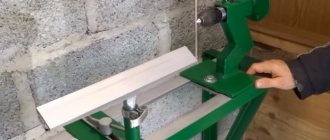
Table for hand-held circular saw with lifting mechanism
To change the depth of the cut, you can additionally install a lifting mechanism (elevator).
Read also: Modulus of elasticity of the first kind for steel
The lifting mechanism itself is mounted from a metal sheet that is attached to the frame on the machine. Lifting will take place along the guides by tightening the bolts.
One way is to install the adjusting rod with fixation nuts. Instead of rods, we use studs. The adjustment handle is made from a plate welded to the end of the stud. At a distance of 4–5 mm from the center we make holes for self-tapping screws. We weld a rod to the edge of the plate, which we will use to rotate the structure.
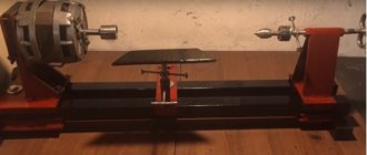
Woodworking jointer with adjustable table
Our website www.umeltsi.ru has repeatedly published materials about woodworking “circular” machines with a circular saw and a jointer, so necessary for home craftsmen.
Based on these publications, I made a similar machine for myself. But when I did it, I realized that not everything about it suits me. In particular, the mechanism for raising and lowering the table. And it was only a stretch to call this device a mechanism.
Introduction
The machine consists of three main structural elements:
- base;
- sawing table;
- parallel stop.
The base and the sawing table itself are not very complex structural elements. Their design is obvious and not so complicated. Therefore, in this article we will consider the most complex element - the parallel stop.
So, the rip fence is a moving part of the machine, which is a guide for the workpiece and it is along it that the workpiece moves. Accordingly, the quality of the cut depends on the parallel stop because if the stop is not parallel, then either the workpiece or the saw blade may become jammed.
In addition, the parallel stop of a circular saw must be of a rather rigid structure, since the master makes efforts to press the workpiece against the stop, and if the stop is displaced, this will lead to non-parallelism with the consequences indicated above.
There are various designs of parallel stops depending on the methods of attaching it to the circular table. Here is a table with the characteristics of these options.
Read also: Autocad gear drawing
| Rip fence design | Advantages and disadvantages |
| Two-point mounting (front and rear) | Advantages: · Quite rigid design, · Allows you to place the stop anywhere on the circular table (to the left or right of the saw blade); · Does not require the massiveness of the guide itself. Disadvantage: · For fastening, the master needs to clamp one end in front of the machine, and also go around the machine and secure the opposite end of the stop. This is very inconvenient when selecting the required position of the stop and with frequent readjustment it is a significant drawback. |
| Single point mounting (front) | Advantages: · Less rigid design than when attaching the stop at two points, · Allows you to place the stop anywhere on the circular table (to the left or right of the saw blade); · To change the position of the stop, it is enough to fix it on one side of the machine, where the master is located during the sawing process. Disadvantage: · The design of the stop must be massive in order to ensure the necessary rigidity of the structure. |
| Fastening in the groove of a circular table | Advantages: · Quick changeover. Disadvantages: · Complexity of design, · Weakening of the circular table structure, · Fixed position from the line of the saw blade, · Quite a complex design for self-production, especially from wood (made only from metal). |
In this article we will examine the option of creating a parallel stop design for a circular saw with one attachment point.
Stationary installation
A machine similar to factory models requires proper handling during the assembly process, so you need to take care of all the little things in advance. The desktop version of the “circular” differs from the stationary one only in the height of the bed, which is determined by the characteristics of the work and the size of future workpieces. One-time processing can also be done using an ordinary table saw, which after work can be easily put away in the pantry or shed. But a craftsman who constantly deals with wood will need a stationary installation. Therefore, he needs to make his own circular saw table.
The circular saw has the following advantages:
- Such equipment allows you to make better and deeper cuts.
- The machine is much more convenient than manual equipment.
From the above, we can conclude that self-made circular saws have a completely understandable and simple design, and the drawings, which can be found on the World Wide Web, will greatly simplify the process of assembling equipment. Before making a “circular” yourself, you should separately consider all the necessary elements in order to understand the nuances of the functioning and installation of home-made equipment.
Preparing for work
Before you begin, you need to decide on the necessary set of tools and materials that will be needed during the work process.
The following tools will be used for work:
- A circular saw or you can use a jigsaw.
- Screwdriver.
- Grinding machine.
- Grinder (Angle grinder).
- Jigsaw.
- Hand tools: hammer, pencil, square.
During the work you will also need the following materials:
- Chipboard.
- Plywood.
- Solid pine.
- Steel tube with an internal diameter of 6-10 mm.
- Steel rod with an outer diameter of 6-10 mm.
- Two washers with an increased area and an internal diameter of 6-10 mm.
- Self-tapping screws.
- Wood glue.
Wood trimmings
A wood trimmer or miter saw cuts the ends of various processed materials. The tool is capable of cutting off unnecessary elements at a certain angle. The advantage of trimming is that when working with it, the workpiece remains motionless, and this allows you to make a neat and even cut.
Grinder machine
Photo of trimming
Many people prefer to do trimming with their own hands. A homemade installation has undeniable advantages, which we will talk about later.
Trimming saws can work on wood, metal, polymers and other materials. But the harder the material being processed, the higher the power requirements for the device.
The most popular trimming is based on the use of an angle grinder. Almost every craftsman has circular tools in his garage or at home, so finding the original tool for wood or metal will not arise.
If you manage to do everything correctly, then your broaching machine, made from a manual grinder, will have the following capabilities:
The rotation speed of the circular disk is 4500 rpm; The length of the cut is about 350 mm.
Diagram of a wood trimming device
If necessary, circular saws are removed from the machine and used with your own hands as a regular hand tool. A huge plus is that a homemade trimmer of this type is universal and can be easily disassembled.
The process looks like this.
Install the angle grinder's rotating device on the turning axis of the machine's wheel. Its fixation is carried out by a ball bearing. Preferably 150mm in size, but larger ones will also work. The ears are welded on the outside of the bearing by welding. They will serve for fixing to the base of the machine. Fasten with M6 type screws. It is recommended to cover the clip with a protective box so that when you work the grinder on wood or metal, shavings do not interfere with you. The issue with broaching is easily resolved. To make it, use another element from a truck - shock absorbers. Even if they are broken, it's not a big deal. Remove all oil from the shock absorbers, make ventilation holes and tighten with mesh to prevent dust and chips from getting inside. Install the soft start module. Due to this, you will not feel sudden jerks when turning on the circular. The assembly of the machine with a grinder-based broach is completed by the assembly of a protection that can protect the saw blade.
Depending on the installed disk, a grinder machine is capable of working on soft wood or metal and cutting the ends of pipes. But be prepared for the fact that the power of your circular saw may not be enough to cut pipes. Focus on the technical parameters of your manual grinder to understand whether the machine can cut pipe elements, or whether the unit is suitable exclusively for woodworking.
This design has two main disadvantages:
To adjust the accuracy of cutting wood with a broaching machine, you need to use scraps of wood. After this, the rod can be firmly fixed and work normally; Such a homemade installation with broaching when cutting pipes and working on metal produces a lot of noise, which can at least negatively affect the mood of your neighbors.
Assembling a complex machine
There is an option with a more complex and heavier design. She can definitely handle cutting pipes. In this case, a homemade installation will not require the use of a circular saw as a component of the machine. But for certain stages of work it is better to have a circular saw on hand.
Depending on the selected components, you can get a machine with increased power. To assemble the machine yourself you will need:
Electric motor with a power of about 900 W. If you have to regularly cut pipes, you can choose a more powerful electric motor; Metal sheet; Metal corners; Channel; Hinge groups; Bulgarian; Welding device; File; Spring of impressive power.
When everything you need has been collected at the workplace, you can begin assembling the cross-cutting machine with your own hands.
A homemade bed can be made with your own hands by using adjustable supports, metal corners and bed posts. A sheet of durable metal acts as a working surface. You need to make holes in this sheet table and process them using a file. To weld a pendulum stand for a future machine, use channels and a welding machine. The structure is installed on a metal sheet. The approximate height of the stand is 80 centimeters. The stand for the electric motor is made of a metal sheet in the form of a fixed plate. Be sure to install the stand on its hinges. The stabilizer of the electric motor of a cross-cutting machine is a powerful spring. If you manage to find one, you can completely abandon the belts and pendulum. Using the eyebolt, you can tension and adjust the belts. The pendulum can be made of metal to make the structure reliable and durable. Use the actuating tool to select a disk of the required diameter. For household purposes, a saw blade with a diameter of 400-420 millimeters is usually sufficient. Be sure to provide protective covers, since assembling such a machine is accompanied by a certain degree of danger.
When choosing the option of assembling a machine with your own hands, rather than purchasing a factory-made cross-cutting machine, you need to understand that there will be quite a serious difference between them in the quality, accuracy and error of processing wood, pipes, metal and other products.
Advantages and disadvantages
Homemade trims have both strengths and weaknesses. Therefore, before starting to manufacture a machine, we advise you to compare the list of advantages and disadvantages. This may make you give up the idea of assembling the machine yourself, or, on the contrary, you should definitely try to make pipe trimming without outside help.
We recommend: How to make a wooden carpentry and metal workbench with your own hands according to the drawings: we are considering the issue
The strengths of homemade cross-cutting machines include:
To manufacture a cross-cutting machine, you will need to invest much less money than in the purchase of factory equipment for trimming wood, pipes, polymers, etc. On average, craftsmen spend 500-1000 rubles to re-equip a grinder into a machine; You can choose the operating parameters for your future cross-cutting machine. These characteristics include the depth of cut, the diameter of the discs, the power of the electric motor, the dimensions of the working surface, etc.; The assembled devices have a simple design. Since you assembled and disassembled the tool yourself, there will be no problems troubleshooting.
But there are also disadvantages, among which these stand out.
For homemade machines, old, unnecessary materials and tools are usually used. This negatively affects the quality and service life. They rarely have high power. In some cases, savings on the purchase of a factory machine become imaginary, since a lot of money is spent on repairs, modernization, and maintenance of a home-made machine. You are taking a safety risk with a homemade trimmer.
Having a grinder for wood and metal at your disposal, you can easily make a homemade machine. Follow the instructions and adhere to safety regulations.
Source: TvoiStanok.ru
| Share on social networks: | Rate this article: (No votes) Loading… |
Design of a circular saw stop
The entire structure consists of two main parts - longitudinal and transverse (meaning relative to the plane of the saw blade). Each of these parts is rigidly connected to the other and is a complex structure that includes a set of parts.
The main technological solution of this stop is the principle of jamming using an eccentric and tightly pressing two transverse guides with an oblique end.
Fixation occurs by turning the eccentric mechanism.
The pressing force is large enough to ensure the strength of the structure and securely fix the entire rip fence.
The entire design is not trivial and consists of a large number of different parts, each of which has its own purpose and size.
From a different angle.
The general composition of all parts is as follows:
- Transverse part
- The base of the transverse part;
- Upper transverse clamping bar (with an oblique end);
- Lower transverse clamping bar (with an oblique end);
- End (fixing) strip of the transverse part.
- Longitudinal part
- Planar sliding element (laminated chipboard, 2 pcs.);
- The base of the longitudinal part;
- Clamp
- Eccentric
- Eccentric handle
Making a circular saw
Preparation of blanks
It all starts with the fact that it is necessary to cut the workpieces to the specified dimensions.
A couple of points to note:
- flat longitudinal elements are made from laminated chipboard, and not from solid pine, like other parts.
- Two blanks of clamping strips are made with “oblique” ends (not 90º, but 63.5º).
Thus, we get the following set of blanks.
Eccentric clamp
Let's start making an eccentric clamp that rigidly fixes the guide.
We glue two blanks measuring 80x80 mm together.
Press with a clamp and let the glue dry. In the toga you get something like this.
Using a 22 mm feather drill, we drill a hole in the end for the handle.
In the center of the workpiece you need to make a blind (not through) hole 5 mm long.
It is better to do this by drilling, but you can simply hammer it with a nail.
The circular saw used for work uses a homemade movable carriage made of laminated chipboard (or, as an option, you can whip up a false table), which is not too bad to deform or damage. We hammer a nail into this carriage in the marked place and bite off the head.
Read also: Thyristor voltage regulator operating principle
Thus, we have an improvised axis of rotation for our part, called the “eccentric” (although in this case, the filled hole is located strictly at the geometric center).
Then, putting the workpiece on an axle made of a nail, we begin to grind off the corners and excess material.
As a result, we get a smooth cylindrical workpiece that needs to be processed with a belt or eccentric sander.
We make a handle - it is a cylinder with a diameter of 22 mm and a length of 120-200 mm. Then we glue it into the eccentric.
Transverse part of the guide
Let's start making the transverse part of the guide. It consists, as mentioned above, of the following details:
- The base of the transverse part;
- Upper transverse clamping bar (with an oblique end);
- Lower transverse clamping bar (with an oblique end);
- End (fixing) strip of the transverse part.
Upper transverse clamping bar
Both clamping bars - upper and lower - have one end that is not straight 90º, but inclined (“oblique”) with an angle of 26.5º (to be precise, 63.5º). We have already observed these angles when cutting the workpieces.
The upper transverse clamping bar serves to move along the base and further fix the guide by pressing against the lower transverse clamping bar. It is assembled from two blanks.
They are collected with glue.
And they are additionally fixed with self-tapping screws.
Lower transverse clamping bar
The lower transverse clamping bar is rigidly fixed to the base and serves to fix the guide by pressing against the upper transverse clamping bar.
Like the top bar, it also consists of two blanks.
We also assemble using glue and screws.
Both clamping bars are ready. It is necessary to check the smoothness of the ride and remove all defects that interfere with smooth sliding; in addition, you need to check the tightness of the inclined edges; There should be no gaps or cracks.
With a tight fit, the strength of the connection (fixation of the guide) will be maximum.
Assembling the entire transverse part
The cross guide bar of the cross guide is directly fixed to the circular table.
A transverse base is attached to this bar.
We assemble the entire structure using glue and screws.
Longitudinal part of the guide
The entire longitudinal part consists of:
- Planar sliding element (laminated chipboard, 2 pcs.);
- The base of the longitudinal part.
Planar sliding element
This element is made from laminated chipboard because the surface is laminated and smoother - this reduces friction (improves sliding), and is also denser and stronger - more durable.
At the stage of forming the blanks, we have already sawed them to size, all that remains is to refine the edges. This is done using edge tape.
The technology for edging chipboard is simple (you can even glue it with an iron!) and understandable.
The base of the longitudinal part
The base consists of four longitudinal elements, as well as two vertical ones for installing an eccentric.
If you break it down into details, you get the following diagram.
We collect the previously sawed blanks for glue.
We also additionally fix it with self-tapping screws. Do not forget to maintain a 90º angle between the longitudinal and vertical elements.
Assembly of transverse and longitudinal parts.
First you need to attach the substrate (longitudinal element) to the upper transverse clamping bar.
We fix it with glue and screws.
It's VERY MUCH here . It is important to maintain an angle of 90º, since the parallelism of the guide with the plane of the saw blade will depend on it.
Then we install the longitudinal base on the substrate.
We also fix it with glue and screws.
Installation of the eccentric
The eccentric is installed between two vertical elements on the longitudinal part.
A metal tube (future bushing) with an internal diameter of 6-10 mm must be placed in the eccentric itself.
We fix it with glue.
In addition to the bushings on the eccentric itself, you need to make similar bushings on the vertical elements, although, as an option (worst), you can use larger washers.
Additionally, a thrust block must be installed for better clamping.
Installing the guide
It's time to attach our entire structure to the circular saw. To do this, you need to attach the cross stop bar to the circular table. Fastening, as elsewhere, is carried out using glue and self-tapping screws.
We install the moving part.
All that remains is to check that the angles are correct, and we consider the work completed.
... and we consider the work finished - the circular saw is ready with your own hands.
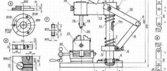
Work progress on the manufacture of a woodworking machine
The table was mounted on four stud posts, and to move it vertically it was necessary to unscrew and tighten as many as eight nuts. Moreover, it was necessary to set the table plane parallel to the axis of the plane (and circular saw) “by eye.” In the end, I decided to make another table, with a more “advanced” mechanism for raising and lowering it (the table).
The base of the lifting table is the frame. Its dimensions are consistent with the dimensions of the top of the circular frame.
The frame is made of steel equal-flange angle No. 6.3 and is collapsible: its transverse elements (I have them 425 mm long) are attached to the longitudinal ones (their length is 560 mm) with Mb screws. But it couldn't be done without welding. At the ends of the longitudinal elements, end plates are welded, cut from 5 mm steel and sawn along the internal profile of the corner. The plates have three holes with a diameter of 6.2 mm, and the vertical shelves of the crossbars have corresponding MB threaded holes through which the elements are fastened with MB screws. In the longitudinal elements, at a distance of 60 mm from the ends and 15 mm from the upper edge of the vertical shelf, two holes with a diameter of 18 mm were drilled for the support bushings of the shafts.
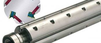
The support bushings are machined from sections of half-inch water pipe, inserted into the holes and welded to the corners. But it is better to do this simultaneously with the installation of the shafts - then it is easier to maintain the alignment of the bushings and ensure ease of rotation of the shafts in them, for which it would be useful to apply grease to the rubbing surfaces.
The shafts (there are two of them) are solid steel rods 430 mm long, machined from a cylindrical rod with a diameter of 18 mm. One of the ends of each shaft is turned into a square with a side of 12 mm - a lever is put on it, with the help of which the table is raised and lowered.
The lever is a handle welded to a cylindrical hub with a central (axial) square hole corresponding to the square at the end of the shaft.
There are also two levers, like shafts. To ensure uniform lifting of the table, the levers are connected to each other by a rod made of a steel strip with a cross-section of 3×20 mm. The rod is mounted freely on axles welded to the levers.
The main elements that raise and lower the table are eccentrics. They are machined from a steel round rod with a diameter of 46 mm. The holes in each of them with an eccentricity of 5 mm were also drilled on a lathe. To do this, when clamping the part in the chuck, a steel plate 10 mm thick was placed under one of the jaws. The table travel (its vertical movement) after this was also 10 mm. The eccentrics are mounted on the shaft and secured to it by welding. Before welding, you must make sure that all eccentrics are directed in the same direction with the same position of the levers.
But before that, bushings with brackets welded to them for fastening the table are put on the eccentrics. In the photo, for clarity of the entire structure, the table is made of plexiglass and attached to the cradle with screws with large (not countersunk) heads. In reality, the table itself is large in size and its edges extend beyond the frame (but only such a sheet of plexiglass was available).
The lifting table frame is mounted on the top members of the machine frame, and both structures are bolted together through corresponding holes drilled at the same time.