All templates are made of St3, 4mm thick.
The templates are marked with: name, the amount of indentation of the template from the line of connection of the workpieces.
General view of the templates:
and parameters (pitch, diameter of the copy sleeve, Enkor cutter code, size of the template indentation from the workpiece connection line)
The quality of the cut can be assessed from the following photos:
Templates are divided into groups in the following sequence:
To work with templates, there are jigs and gauges that make setting easier.
The following tables indicate the names of the templates and their parameters:
Templates called ISOLOK allow you to make connections with the following profiles:
The pitch is from 24mm to 63mm (depending on the profile), the minimum thickness of the workpiece is 16.3+-0.5mm, also depends on the profile, the maximum is determined only by the working length of the cutter. All templates are made for an 8mm cutter and a 12.7mm sleeve.
Source: pekas.ru
Types of tenoning machines
A tenon saw is a type of woodworking machine. There are samples of both imported and domestic production on the market. The fixing elements on it can be processed for subsequent connection of products at an angle, as well as for their merging (dovetail folds are used).
Machines for milling tenons are divided into frame machines and box machines according to their intended purpose.
In this case, frame units are:
- unilateral In one pass, the tenons are processed on one side of the workpiece;
- two-way automated. The design of a tenoning machine involves placing supports on two columns and, accordingly, processing the workpiece on both sides.
Naturally, the productivity of double-sided tenoning machines is much higher than their analogues. There are several types of units, which differ in length, and they come in 2, 2.5, and 3 meters.
The cutting tools for them are cross-cut saws and cutters (disc and end) for processing straight tenons, lugs on frames and frames of various wooden structures.
The formation of box and dovetail tenons is done on specialized machines, mainly in large-scale and mass production. At the same time, there are two types of dovetail fixation: with rounded and sharp corners.
The first category is produced on multi-spindle tenoning machines. Such shaped protrusions are processed simultaneously on the mating surfaces using modular cutters. It is this connection that guarantees the durability and reliability of the fixing unit.
When producing the most complex oval dowels (small tenons) and those with a round shape, automatic tenoning machines with numerical control are used.
Manufacturing of equipment for box connection
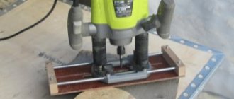
This product allows you to mill box joint grooves one at a time on a milling table. In our case, it is simply an additional board, screwed onto an angle stop and having a key, with which we will determine the exact interval between the grooves.
simple device for making box joints
Install a straight cutter with the diameter of the required groove width; Place the router on the table. Set the routing depth equal to the thickness of the existing board and mill a groove into it. After this, unscrew the board from the miter gauge and move it so that the gap between the groove and the cutter is equal to the width of the cutter.
Mill a groove in the board again, this time the second one (on the right). Cut a key out of the wood so that it fits exactly into the first groove and place it on the glue, so that it will be approximately 25 mm from the groove on the additional board.
Milling grooves in the first workpiece
Place the workpiece with its front surface against the additional miter fence board, pressing one of its edges against the key. Turn on the router and, holding the workpiece firmly against the fence, move it onto the cutter, milling the first groove. U
Specifications
The operator’s functions when working on an automatic machine are reduced to loading and turning workpieces, starting or stopping the cycle. Important indicators of tenoning units are:
- largest peg size;
- the smallest thickness;
- groove height;
- width;
- maximum workpiece size;
- spindle speed;
- engine power.
In addition to the characteristics for classifying the machine, the parameters of the cutting tool are indicated: saw diameter, type and size of cutter.
Often on large production lines such equipment is installed to the ceiling. The machines are additionally fixed with clamping devices, where the workpieces are processed by scoring saws, followed by the formation of tenons on milling supports.
The feed is adjusted smoothly using a variator. To create a high-quality surface of the mating elements, the spindle speed should be about 700 rpm.
Principle of operation
When forming pegs, a sawing and milling procedure is usually used. An appropriate cutting tool is used to obtain the tenon joint surfaces.
Attention! Whatever the shape of the tenons, the initial operation is to trim the workpiece.
For the most common models that use milling during processing, the machines are equipped with four spindles - three milling and one sawing. One or more workpieces can be loaded onto the carriage table, and they are aligned with their edges along the ruler and their ends along the stop bar.
The tenon is formed as a result of end milling. When the cutting tool comes out, chips may appear on the edges, so to prevent them, a support block is mounted on the ruler, and some machines also provide for the application of glue to the surface being processed.
After turning on the feed mechanism, the product is automatically fixed due to the side and top hydraulic clamps. The carriage with the workpiece begins to move at a certain speed along two guides relative to the cutting tools.
In this case, during the movement of the carriage, a spike of the desired configuration is formed on the structure, then the device, having reached the stop (limit switch), returns to its original position. Here the finished product is replaced with a blank, and the cycle repeats again.
If the machine is double-sided, the process of forming tenons occurs on both sides of the workpiece.
Homemade tenoning machine
Today there are all opportunities for entrepreneurial activity, while many are engaged in the manufacture of furniture, wooden doors and windows, where connecting tenons are indispensable when assembling the product. And since tenon cutting machines are not cheap, at first a homemade unit is quite suitable for obtaining fixing elements.
It is easy to make on your own, which will save a lot of money when organizing production. Moreover, there are different options for the manufacture of such machines, where the basic element can be a stationary engine, an angle grinder, a jigsaw, and even an electric drill.
Let's consider making a do-it-yourself tenoning machine based on a grinder with a disk cutter positioned in a horizontal position.
As in a factory machine, here, in addition to the engine and cutting tool, there are two components:
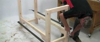
The frame must be strong and stable, since it is the base part of the unit on which the device for fastening the workpiece and the grinder with the cutter are installed. This component of the tenoning machine can vary in design and be manufactured without drawings. For example, it can be made from metal corners, and a sheet of chipboard can be fixed on them.
The size of the tabletop must correspond to the intended workpiece. It also contains clamps and a control ruler.
The bed guides must be strictly perpendicular to the movement of the tabletop when milling connecting elements. The quality of the connection between the studs and lugs depends on this.
Start with the Basics: Basic Rules for Male-Socket Joints
Regardless of how you form your tenons and sockets, these tips will help you achieve perfectly-fitting, strong joints for any project.
- Correct connections always start with careful markings. Use a proven steel ruler and square, and mark the marking lines with a sharp pencil, surface planer or marking knife.
- A simple rule that is easy to remember: when marking a socket on the end or edge, the thickness of the workpiece must be divided into three equal parts. The outer two thirds will become the walls of the nest, and the middle third must be removed. So, in a board 18 mm thick (picture below), a 6 mm wide nest is made in the center of the edge of the workpiece. When using material with a thickness of more than 18 mm, the width of the socket can be more than one third of the thickness of the workpiece, provided that the thickness of the walls of the socket is at least 6 mm - this is due to strength considerations.
- Fitting a crossbar tenon to a socket with rounded edges is easier than making a rectangular socket. To round corners, use a rasp or a knife with replaceable blades.
First make the nests, and then form the spikes that match them. It is much easier to precisely adjust the tenon than to change the dimensions of the finished socket.
- The highest bond strength is achieved when the mating surfaces are smooth.
- A correctly fitted tenon should be held in its socket without glue and should not fall out when parts are turned over, but at the same time, only a small amount of hand effort should be enough to assemble and disassemble the joint.
- Drilled or milled sockets will have rounded ends. To fit them to a rectangular tenon, you can trim the corners of the socket with a chisel. To save time and effort, you can simply round the corners of the tenons (photo on the right).
Machine assembly
The location of the shaft exit is determined on the table surface and a hole of a slightly larger diameter is made. The grinder is fixed with clamps, and you need to make sure that the heads of the bolts are flush with the plane of the table top.
Disc cutters are used as cutting tools. In this case, one cutter is used to select the eye and two cutting discs if it is necessary to process the tenon. Accordingly, the distance between the cutters is equal to the width of the groove.
Important! If two disc cutters are used, the fit on the grinder should be through an adapter with keyways.
With this assembly, the process of milling an eye or tenon occurs due to the movement of the workpiece. To do this, it is attached to the tabletop with clamps and then manually moves along the frame guides to the rotating cutter. In this case, the dimensions of the stud and eye are achieved due to the stops and the thickness of the washer between the discs.
Device for milling the dovetail-dovetail joint
The illustration shows a tooling that allows you to mill a series of evenly spaced slots for straight or dovetail inserts. Cut a V-shaped notch in the workpiece, then install a 3/4-inch straight bit in the router and set the tool in the router table.
equipment for making a dovetail-dovetail connection
Screw the equipment to the miter gauge and feed it onto the cutter to make a turnkey groove. Install and glue the wooden key into the groove, reinstall the device on the miter gauge so that there is a distance between the key and the cutter and it is equal to the interval that you want to make between inserts.
Feed the jig onto the router bit to mill the second slot. Install a 1/2-inch dovetail bit and adjust the depth of cut so that the full dovetail shape is above the base of the recess.
To use the jig, clamp the workpiece into the V-shaped notch of the jig, pressing the workpiece against the key, and rout the first slot. To mill the next grooves, just move the workpiece with the groove onto the key, and you can feed the workpiece to the cutter again.
Assembling the turning fixture
Scheme of a simple lathe.
The assembly method will be like this:
- The basis of the unit will be a 3-phase electric motor. Therefore, its power supply must be three-phase, otherwise the automatic fuse in the house will constantly blow out.
- Engine speed is no more than 1500/min.
Note! Different types of drives are connected differently: “triangle” or “star”. The main difficulty in this case is the correct choice of capacitor. Its capacity must correspond to the power of the engine.
- Place a faceplate on the motor shaft for large parts and a removable analogue for small ones. Secure the other side of the knot with a corner. There are special peaks on the faceplates; the workpieces are pressed onto them with a hammer.
- Next, center the workpiece and secure it with counter washers. The homemade woodworking machine is ready.
Working on the machine
The photo shows the production part.
- Turn on the machine and insert the first cutter (ordinary chisel). It will remove the initial layer (1-3 mm).
- After rough processing, the workpiece will be 1 mm thicker than necessary. Remove the remaining layer with a finishing cutter, which will give the product its final shape.
The dimensions of the workpieces can be controlled with a micrometer or a template. Contours and cuts can be made with the sharp side of a chisel, and grinding can be done with a finishing cutter.
You can also smooth the parts with sandpaper. Polish with wood shavings, holding them in your fist and bringing them to the workpiece.
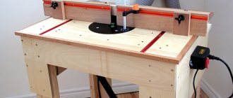
Milling table
To make it convenient to work with a hand router, it is often mounted permanently, while the workpieces are moved. In this case, the tool turns into a milling table.
Tool selection
Before choosing a manual wood router, think about what operations it will be needed for:
- Homemade woodworking machines for complex workpieces require a powerful milling cutter with a high number of revolutions.
- It is advisable to purchase a tool with manual adjustment and auto-stabilization of the spindle.
- Convenient units have soft start and quick shutdown options.
Note! The instructions recommend selecting a device with a power of at least 2 kW and with speed control. This way you can confidently process any species and type of wood.
Manufacturing of the unit
Milling table diagram.
An important element of the machine is the frame:
- It consists of a frame on supports, with a table top placed on top of it. The frame can be made from any durable material: chipboard, wood, metal, etc.
- The main thing here is that the structure is stable and rigid. As for the size, you need to proceed from the volume of workpieces you will have to work with.
- For ease of use, the bottom of the bed should be deepened. This will allow you to avoid clinging to the structure with your feet.
The tabletop can be made from a regular analogue for a kitchen table, coated with a special plastic. Thanks to it, the part will glide well, and the board will perfectly dampen vibrations.
Next you need to make a mounting plate for the router:
- It must have a high level of strength with a small thickness. Textolite and metal meet this condition. What the drawings convincingly prove: how to make woodworking machines yourself.
- The plate should have a rectangular shape. A hole is made in its middle, then the router is fixed in this place.
- To attach the unit with the plate to the tabletop, 4 holes are drilled in the corners of the metal or textolite.
For ease of work, you can equip the table with an upper clamp. A ball bearing is useful for this. It will make it possible to tightly fix the parts.
Universal machine made from an electric drill
Circular from a drill.
For household use, you can assemble a universal unit that combines many home-made machines and tools for wood: a circular saw, a sharpener, a cutting device, a lathe and a grinder.
Assembly of the unit
The assembly will consist of 4 steps:
- The basis of the device is a frame for fixing the drill. Its material is boards, textolite (thickness 1.8-2 cm) or 2 sheets of plywood glued together (1 cm each).
- The drill is attached to the neck (it is cylindrical) of the body, the purpose of which is to install an additional handle. Clamping principle: the gap (in the frame) is tightened with a rigidly threaded nut and pin.
- The number of installation points for an electric drill, their location on the frame and dimensions depend on the type and size of the tool, as well as its use. You can clamp emery, saw blade, cutters, flexible grinding wheel for wood, etc. into it.
- The pin can be rigidly fixed using epoxy glue with additional protection against rotation (pin with a cross-section of 2 mm).
Application of the device
Drill-based lathe.
Such self-assembled woodworking machines have a wide range of applications. Drilling wood goes without saying, because... The basis of the device is a drill.
The second purpose is sawing sheet materials: plywood, chipboard, fiberboard. To do this, in addition to the drill with a circular saw with a cross-section of 15 cm fixed in the chuck, you need to secure a sliding sole at the bottom on the bed.
It can be made from duralumin 2 mm thick. For comfortable use of the resulting electric saw, you can make a handle at the front of the top of the frame.
Please note! The saw blade must be covered with a protective cover. It can be made from a bent steel strip (2-3 mm thick), securely fixed to the frame.
The third option is to replace the disc with a flat cutter. This will make it possible to cut not very deep grooves. Here you need to additionally make a rectangular hole on the sliding sole.
The fourth option is to use a circular saw as a cutting unit. This is convenient for the production of door frames, window frames, etc. It is best to do this on a support plate with a rotating bracket fixed to it.
The fifth way to use a drill is as a drive for a small woodworking machine. In this case, the sliding sole will act as a desktop. In this case, the frame is fixed with corners on a support plate made of OSB or chipboard.
This rigid design makes it possible to assemble both a small turning and a grinding unit.
Make the nests first
Method No. 1. Simple drilling jig for dowel connections
The first two methods of removing nests involve drilling a series of overlapping holes and removing excess material between them. The holes should be perpendicular to the edge of the board, and jigs for drilling holes for dowels do an excellent job of this task. They are especially convenient when working with material with a thickness of about 18 mm, for which bushings with a common diameter of 6 mm are suitable, just corresponding to the width of the socket. (Most of these tools have bushings for drilling 6, 8, and 10 mm diameter holes, and some have a bushing for 12 mm diameter holes.) If the drill jig did not come with a drill bit, purchase a twist wood drill bit with a center point - this will cut cleaner and not gives chips on the surface.
To limit the depth of the hole, attach a locking ring to the drill or make a “flag” out of masking tape.
Holding the chisel perpendicular to the edge of the board, carefully cut away any rough edges on the sides of the nest. If the chisel is sharp, you won't need a mallet.
To make a nest, attach the jig to the workpiece, positioning it at the edge of the marked nest so that the edge of the hole just touches the marking lines marking the edge and walls of the nest. Drill a hole, having previously set the required drilling depth. Do the same at the other end of the socket, as shown at the top left. Now rearrange the jig and drill a few more holes between the two outer holes. After this, drill out the material between them, centering the drill on the bridges between them.
After removing most of the excess material, clean and level the sides of the socket with a chisel. Use the widest chisel that the size of the socket will allow. If you prefer rectangular sockets, trim the corners with a chisel that is the same width as the socket.
Method number 2. The same principle, but using a drilling machine
The bridges left between the holes are needed to allow the drill to fit in when removing excess material.
If you have a drill press, then for greater productivity and accuracy, use it instead of an electric drill and drill jig. You will need a stop (at least in the form of a flat board attached with clamps to the machine table) to position the socket and ensure that it is parallel to the edges of the workpiece. Using a square, check that the table is perpendicular to the drill. Install a pointed twist drill or Forster drill into the machine chuck; the central point of such drills prevents the drill from leaving the intended point. Adjust the drill depth stop to match the depth of the socket.
Just as when using a jig, first drill holes at the ends of the future nest. Then drill a series of holes between them, leaving bridges about 3mm wide. After finishing drilling, trim the walls and corners of the socket with a chisel.
Method number 3. Using a plunge router
This technique involves milling the socket with an increase in depth of 6 mm for each pass. In addition to the plunge router, you will need a sharp router bit (we recommend a helical router bit with an ascending helix), as well as a side stop or special device to hold the router within the marking lines. You can control the starting and ending points of the milled nest by eye or attach stop bars to the workpiece that limit the longitudinal stroke of the router.
A homemade or factory made socket routing jig like the one shown above is a versatile addition to any workshop. The top plate made of transparent plexiglass allows you to easily align the centering lines of the fixture with the markings on the workpiece. The length and width of the slot hole of the device should be slightly larger than the dimensions of the socket, taking into account the difference in diameters of the cutter and the copy sleeve moving in the slot hole. The additional costs of purchasing a ready-made device are compensated by its quick installation and flexible configuration of nest sizes. Examples of such devices are the Mortise Pal and Leigh Super FMT. The Mortise Pal has a built-in clamp and comes with six templates for routing sockets of varying widths and lengths (additional templates can be purchased separately). The Leigh Super FMT bench jig (www.leighjigs.com) allows you to rout both socket and tenon in one setup. The kit includes guides and cutters for tenons and sockets in five different sizes. Additional guides are purchased separately.
EDGE OF THE BLANKET. When machining narrow workpieces, such as this stand, use a clamp to hold down an auxiliary piece of wood to stabilize the router. END OF THE BLANKET. A simple device creates a wide and stable support surface for the router when making holes in the ends of workpieces.
Method number 4. Drilling square holes is easy
Of course, from a technical point of view, a slotting machine does not perform drilling, but rather the chiselling of square holes. A rectangular socket is hollowed out around a round hole simultaneously with drilling the latter, for which a special auger drill is used, located inside a hollow cutter-chisel (delicate photo on the left). This method of sampling nests is the fastest, but also the most expensive. Tabletop slotting machines, which cover almost all of your nesting needs, cost around S225-500, with floor-standing models starting at $900. (Keep in mind that some specialty machines do not come with cutters and drills, which cost $10-$30 each, with sets of four starting at $40.)
The drill has deep grooves that quickly remove chips, and the external square cutter-chisel forms clean walls of the socket.
The long arm of a slotting machine creates the force necessary to drive the cutter into the workpiece.
Once you set up your slotting machine, you can select such a socket in less than a minute.
This is how a slotting machine works. First, install a chisel with a drill into the machine. Adjust the depth stop to match the depth of the socket. Align the fence parallel to the cutter so that the latter is exactly between the marking lines. Form the ends of the nest first and then remove the material between them by making overlapping holes. If you like this method but aren't ready to invest in a dedicated machine, consider purchasing a slotting attachment for your drill press. Such devices are relatively inexpensive ($65-125). The attachment is installed on the machine quill (photo below) and works exactly the same as a slotting machine. The disadvantage is that you will not be able to use the machine for normal drilling until you remove the attachment.
In just 20 minutes, you can turn a drilling machine into a slotting machine by installing an attachment on the quill.
Do-it-yourself tenoning
Therefore, I decided to assemble a jig for making tenon joints using a hand router. The idea was to make a device for quickly and conveniently cutting grooves for Domino insert tenons, because... ready-made solutions are too expensive. It all started with searching for a suitable idea on the Internet. Next, adapt the idea to your needs and, finally, execute the drawings. The operating principle is simple (see next photo).
The position of the groove relative to the edge of the workpiece is adjusted using the blue stop. It will be used as a special cabinet. The width of the groove is determined accordingly by the width of the cutter, the length of the groove is determined by the position of the brown latch. The black part is a 40 mm wide copy sleeve that fits in the resulting groove.
Next is the search for material. It seemed to me a good idea to make a jig from a 6 mm duralumin sheet. Although, probably, it can be made from any sheet material - plywood, plexiglass, textolite. The search for a suitable duralumin sheet at the local poultry market and at local metal collection sites did not yield any results: “Suitable pieces sometimes slip through, but now they don’t and it’s not known when they will. Call back later". We managed to find the required material at metal warehouses. They even offered to cut it to size, but the problem is that they would have to take the entire sheet. And this is, firstly, expensive, and secondly, what should I do with the remaining 70% of the sheet. As a result, I found an individual entrepreneur selling D16T duralumin sheets at retail on the Internet. https://dural16.ru/. Maybe someone will find it useful. You can order a piece of duralumin sheet from them of the required size and thickness. But not everything is smooth here either. If you take not the whole sheet, but a part, then there is a serious markup. I bought from them a suitable duralumin sheet 800×500 with a thickness of 6 mm for 4130 rubles, i.e. 614.58 rubles per kilogram. Yes, quite a lot.
In parallel with the search for material, the search for a turner-milling machine began. I scoured a couple of all-Russian thematic forums in search of fellow countrymen. As a result, I found a couple of dozen accounts to which I sent personal messages. Of these, eight people responded, to whom I later sent drawings with a question about the cost of the work. The price range for working with my material was significant - from two to eight thousand rubles.
As I said above, such a tenon cutter can be made from any sheet material. For example, from plexiglass, PCB or plywood. In this case, you can get by with a simple hand milling cutter. I decided to make my tenon cutter from duralumin, so I had to turn to specialists. It was for them that precise drawings were made with dimensions that might seem redundant and complex to some (although upon closer examination it becomes clear that this is not the case). These dimensions are selected in accordance with the dimensions of the router's side and for a specific copy sleeve. Making it from duralumin is not the cheapest solution both in terms of the cost of the material and the cost of work, but it suits me. It’s interesting to watch how a product you imagined and drew in 3D materializes and becomes a real product.
As you can see in the next photo, the finished product is very simple. When assembling it I encountered an unexpected difficulty. The fact is that in the original design the plates are connected with aluminum rivets with a countersunk head. It turned out that finding such rivets on sale is not a trivial task. They are not only available in ordinary hardware stores, but even in highly specialized hardware stores. I had to connect the plates with regular blind rivets.
The most cunning element of the design is the retractable tongue, which adjusts the length of the groove for the tenon. The whole trick is just the need to adjust the dovetail. Otherwise, there are no difficulties in its manufacture. To make it shorter, not one, but two holes are made in the main plate into which a fixing bolt is inserted, depending on the required size of the groove. In this case, the position of the groove on the tongue itself is chosen in such a way that, in any position of the tongue, the sole of the router does not rest against the locking wing nut.
To attach the tenon cutter, I assembled a cabinet from 21 mm plywood, shown in the following photo. In the upper part of the cabinet there are two parallel grooves for fastening the plate with M10 bolts, in the front part there is a hole for fixing the workpieces on the tenoning machine using clamps.
To give the cabinet the necessary rigidity, I made an additional crossbar inside.
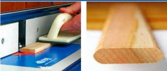
After assembly we get such a device. Before installation, I first matted the metal surfaces in contact with the router sole and with the workpieces using 120 and 240 sandpaper.
Under the plate I attached a strip of duralumin to the cabinet. This strip expands the possibilities of attaching workpieces to the tenon saw using clamps.
So far I have not had the opportunity to give my tenon cutter a real test, but I think it will cope with its task. I will make the inserted spikes, despite the fact that you can buy them ready-made (https://www.kalpa-vriksa.ru/catalog/vstavnye_shipy_domino_dlya_festool_df500/) myself. Still, the cost of one spike is almost 10 rubles - a little expensive.
Characteristics: Dimensions - 250x440x112 mm Weight - about 5 kilograms Max. cutter diameter - 37 mm Max. groove length - 154 mm Thickness of the base under the router - 12 mm
Using this tenon cutter I made a children's bunk bed
Using a tenon cutter, you can make grooves for insert tenons in the desired place on the workpiece
If it is not possible to secure the workpiece to the tenoning saw, then the movable part of the tenoning saw is removed and attached to the workpiece.
If there is a need to process the ends of long workpieces, the tenon cutter can be placed on its side.
The tenon cutter is quite convenient to use and the result is quite high quality.
PS
In the comments they wrote to me about another tenon cutter made according to these drawings. The original message can be found below. I’ll just give a summary: . there is no need to contact different masters. I made a tenon cutter according to your drawings in one day from an aluminum sheet 4 mm thick. 4 mm is the best option for making it yourself. I used a hand router, a circular saw, a file and an electric drill. I just attached another aluminum plate to the plywood bed at the bottom. It’s better to fasten the milled part this way, pressing it against the top and bottom plates. Aluminum can be cut well with a circular saw and a hand router at low speeds. Milled with an 8 mm milling cutter for metal.
Universal device for tongue and groove connection
factory plate for making a tongue and groove connection
Used with a router to cut the corresponding grooves and tenons, it is installed in a vice and the part is pressed against the device with a clamp. Typically sold in stores.
connection appearance
Consider devices for milling grooves
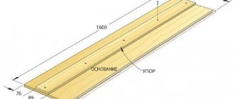
Cut out the top part - a tabletop from 18 mm plywood, 40 cm long and sufficiently wide to process the thickest workpiece that you plan to join with a tenon.
Cut two 5x10 cm bars, sawing them to the same length as the top. The bars will subsequently play the role of pressing the workpiece and centering it relative to the groove in the tabletop. To prepare the top, draw a line down the center of the top, then rout a mortise along the line at one end.
schematic representation of equipment
To use our equipment, draw a groove on the workpiece and mark the center line on it. Loosen the screws and place the workpieces between the bars so that the center line is connected to the top line of the jig, check that the edge of the workpiece is opposite the edge of the top.
Pinch the lambs. Align the router bit to one end of the mortise drawing, then mark guide lines on the top surface of the table along the edge of the router base.
How to work correctly with tongue and groove equipment
Repeat this again to mark the lines of the other end. Route the slot by starting the cut at the bottom by aligning the router base with the first construction line, and stop routing when the insert reaches the second construction line.
Let's make a device for making spikes with our own hands
Product for making spikes
The wood and plywood jig shown above allows you to cut rectangular tenons with two shoulders. The object being processed is located with its front surface underneath the jig, while the router moves along the stop from above, removing excess in two passes.
The piece consists of two parallel base bars, a stopper and a stop - all made from wood of the same thickness as the piece, in this case from 25x75mm bars, and a top surface and support made from 18mm plywood.
The base bars should be approximately 400 mm long; cut out the top surface of plywood approximately 200 by 250 mm and screw it to the bars as shown in the figure. Screw the stopper onto the ends of the base bars along with the support. Place the stop approximately 25mm from the end of the top surface.
cut out the tenon using the device
Countersink holes for all screw heads and make sure all corners are square. Drill an inspection hole in the top surface to accurately position the workpiece exactly according to the markings.
You also need to make a plate from plexiglass. It should be at least as wide as the base of your router and long enough to extend from the stop and beyond the jig stop: 250 by 300 mm will be sufficient.
Install the 3/4-inch router bit, then remove the standard plate from the tool and use it as a template to mark the screw holes and router bit hole in the plexiglass plate.
To start using the product, press the end of the workpiece against the end of the stopper and against the base block. Clamp it all together with a clamp. Set the depth of cut on the router and rout the part to half a tenon, moving the insert along the fence throughout the cut. (You'll also be cutting through the base bars at the same time.) Turn the piece over and repeat to finish the tenon (bottom).
Design features and principle of operation
Tenoning machines belong to the category of woodworking machines and are designed for the automatic production of connecting elements of joinery and furniture structures - tenons and lugs. Depending on the method of wood processing and the type of tenon being made, they are divided into two classes - for the production of frame tenons and for the production of box tenons.
In turn, depending on the technology for manufacturing parts, these woodworking machines are divided into single-sided and double-sided. With their help, the production of studs of all types is automated:
- straight;
- round;
- oval;
- "dovetail".
All mechanisms that a wood tenoning machine is equipped with are arranged in a certain order, corresponding to the sequence of technological operations. The first technological operation performed on wood is trimming. The operation is performed using a special saw mechanism. Next, if the production technology requires it, the lugs are cut into the wood using a special lug head.
After making the eye, two tenoning heads are put into operation, configured to produce a tenon of a certain shape and size. Each saw head is equipped with its own electric motor.
Almost all major furniture manufacturers install the latest equipment for processing wood of various species, automated CNC machines, in their woodworking shops. Replacing the cutting tool and adjusting the technological chain are carried out by the operator and take minimal time.
Some design features
Single-sided units are classified as positional. The workpiece being processed is mounted on the work table of these machines. During operation, the work table moves under the saw heads, which perform the specified manipulations. After the workpiece has completely passed under the cutting tool, the carriage returns the work table to its original position, the workpiece is turned over, and the previous cycle is repeated, but on the other side.
Double-sided units are classified as position-through units. In these machines, the workpieces are fed continuously by a chain conveyor with a mechanism that fixes the workpiece in the desired position; cutting is carried out simultaneously on both sides. Their design includes two columns, one of them is fixed, and the second is movable. Its movement is carried out along guides and is adjusted to a workpiece of a certain length.
Horizontal cutters are used as tenoning equipment, and conical end mills are used in the manufacture of dovetails.
How do wood tenoning machines work?
The production process is divided into a number of sequentially performed operations. First, the wooden blank is placed on the work table, where it is cut to the specified size. Tenoning devices or special saws necessary to perform specified operations are mounted on the working head, located on the frame.
At the same time, a layer of adhesive is automatically applied to the surface of the wood to prevent splitting and chipping. This is a necessary procedure that minimizes the occurrence of defects during processing and, as a result, the yield of defective products.
The next stage of processing is trimming. To perform this task, the wood tenoning machine is equipped with appropriate mechanisms. This is necessary to align the ends. Next, the workpiece is fed under the working heads, where the specified operations are performed using sawing tools.
After completing all technological operations, the output is a part of the required dimensions, with spikes or eyes made in accordance with the specified settings.
Large tenoning woodworking machines are needed for large-scale production. For the production of small batches or single products, small milling machines equipped with tenoning carriages may be quite suitable. This expands the capabilities of the milling machine, since, in addition to its main functions, it also receives the function of a tenon cutter, which is important when producing small batches.
DIY accessories for a wood router: stops, templates, guide rails
For accurate operation, a milling cutter requires auxiliary devices; at the same time, the sales package of the device includes a limited set of such items.
The market for milling attachments extends from protractors to numerous attachments. The user, for whom this is not enough, can make auxiliary devices himself.
Rip fence
The list of useful accessories for a wood router is quite long. Many tool owners are able to make them from scrap materials or, if more convenient, simply buy them separately.
One such device is a rip fence. This is a component of the basic set of any router, and the owner of the tool does not have to make the stop himself. It is needed to directly follow the cutter along the surface of the base, which can be the smooth edge of a part or a workbench.
The stop allows you to process edges and grooves, firmly fixing the part.
This useful addition to the milling tool consists of the following parts:
- rods entering the recesses on the router;
- screw fasteners that tighten them in the desired position;
- adjusting screw for fine adjustment of the distance of the cutter axis from the edge;
- the supporting part that holds the structure to the base.
To make the wood router stop ready, the rods must be positioned in the recesses on the tool body and tightened with a stopper. By loosening the stopper, you can use the adjusting screw to make minor adjustments if necessary.
With a little addition, the rip fence allows you to make, in addition to straight cuts, more complex ones. This addition is a wooden block with one flat side. The other side has an angular or round notch. The block is inserted between the supporting part and the edge of the material, which has a curved shape.
The block is in contact with the support with its smooth edge. The side where the notch is is in contact with the curved base. A tool with such a device should be manipulated with extreme care, since the block introduces an element of instability.
Guide rail
Having a similar purpose to the rip fence, the tire is responsible for the accurate movement of the cutter in a straight line. The time spent on work is noticeably reduced due to the use of the tire. It also allows you to guide the tool on the table at any angle to the edge.
Note! You can secure the tire to a tabletop or material using clamps.
Some mass-produced tires include a separate component - a shoe. It is connected to the router by rods and, passing along the bus, moves the milling head along a given path.
The tire is best combined with a tool whose base stands on retractable legs. This eliminates the height difference between the guide rail and the router.
It happens that the functionality of commercially produced tires is not suitable for the user. You can always create an individual version of the router guides with your own hands. The most elementary one is a long, even beam - in other words, a ruler. The master only needs to provide it with fasteners, and the tire is essentially ready. To make a simple device, you don’t even need a drawing.
Of course, such a homemade version will not be stable. The combination of a plywood base with a board nailed to it will be more stable in operation. The edge of the router base will rest against the board, and the edge of the base will mark the processing area. This design is used when using cutters of the same diameter.
Another option works when wood cutters can be of different sizes. Here the board acting as a ruler is not nailed to the base, but is reinforced with clamps. Thanks to this, it can adjust the distance from the working area according to the diameter of the cutter.
Templates and copy sleeve
The copying ring is a circle with a protrusion that slides along a template, guaranteeing accuracy of processing. The ring can be screwed to the base of the router or secured with antennae. The diameter of the device is selected so that it does not come into contact with the working part of the tool.
The ring template is fixed on the material being processed, firmly adhering to the tabletop. Reliable clamping is provided by double-sided tape and clamps. Having finished the part, you need to make sure that the sleeve fits tightly along the edge of the template when working.
A self-made template for a router can also be used for processing the corners of a part, when it is necessary for them to be round. Depending on the location and dimensions of the template, the radius size of the rounding can be any.
The template design often includes bearings or rings. If this is a ring, then it should be selected according to the size of the cutter. If there is a difference in diameters, it is necessary to add stops to the template design, with the help of which you can move the device away from the edge of the part.
Among the auxiliary devices for the router, the most flexible templates, in addition to processing the edges of the material, also allow you to cut complex grooves. The special design of the accessory makes it possible to effectively create recesses for door hinges. Using a template, you can even carry out decorative work with a router, for example, cutting out wooden patterns.
Compass
This auxiliary tool is designed to create round and oval cutouts. The basic compass design includes a rod with a pin fastening at the end. By inserting the fastener into the hole in the center of the circle along which the groove is made, you can change the size of the circle by simply moving the rod.
Note! The convenience and reliability of the design is increased by adding a second rod.
There are various auxiliary elements that work on the circular principle. They offer the advantage of creating different radii of circular grooves. A mandatory component of such auxiliary devices is a pin with a screw for adjusting the length of the radius.
If a small hole is cut, the compass structure must be adapted for mounting on the base of the router. When processing a part, the pin is located directly under the tool.
A wood router, in addition to round ones, is also capable of cutting elliptical holes. The device for this can be assembled with your own hands from the following parts:
- base with fixation on material made of screws or suction cups;
- shoes moved on crossing guides – 2 pcs.;
- rods for installation – 2 pcs.;
- bracket for connecting the structure to the tool.
The fastening bracket, thanks to the grooves intended for this purpose, allows the frame of the structure to be in the same plane as the base of the router.
Cutting round openings is done using one shoe. If you need an oval hole, both are used.
This auxiliary design makes it possible to make holes more accurately and faster than other tools, such as a band saw or jigsaw.
For grooves on narrow surfaces
Recesses for locks or door hinges can be made with a drill and chisel, but a router is much better suited for this. You just need to equip the tool with a certain device.
It consists of a flat plate that is attached to the base of the device. The shape of the plate can be round or rectangular.
2 pins are made on it, ensuring smooth movement of the tool during operation.
The main parameter that must be adhered to when manufacturing such an element is that the axis of each pin must be on the same line as the center of the cutter.
If this parameter is observed, the groove will be cut exactly in the middle of the workpiece, regardless of thickness.
If it is necessary to shift the groove to the right or left, a sleeve of the size needed for the desired shift is put on the corresponding pin.
Using this design, the router is driven with the pins tightly pressed to both sides of the workpiece.
The same effect is achieved if you use two parallel stops with a router.
Even one stop may be enough. It is necessary to strengthen the workpiece between two surfaces, for example boards, so that all three elements are in the same plane. In this case, the problem of insufficient part width is eliminated.
When you often have to work with narrow surfaces, a good solution would be to build a special table of two halves. By pressing the material between them, the master can easily achieve the effect of one plane.
Bodies of revolution
When working with round workpieces, such as posts or balusters, a structure is made up of a frame into which the part is placed, a carriage for the router and a rotary disk. The part is inserted into the frame, securely fixed, after which the carriage with the tool is pulled out to the processing area. The position of the part in the frame can be changed using a rotary disk.
The same frame with a router in the carriage can serve as a lathe. You just need to turn the disk while simultaneously operating the milling cutter moving along the guides. This can be done by a master’s assistant or a drill connected to the disk.
Tenoning devices
Such devices ensure the creation of joints based on spikes. Such profiles, which require high precision in processing the material, are easily made with a milling machine.
Using a hand router, the master moves it freely to the material. Therefore, the material needs to be securely fastened for error-free tenoning.
Such conditions can be created by a simple device made from the following parts:
- rigidly fixed guides, lower, upper and side;
- a bar with one degree of freedom that will limit the sample.
The parameters of the parts depend on the specific tool for which the device will be assembled. The assembly procedure is as follows.
Along the edges of the plywood base, vertical ribs of equal size are installed with cutouts in the center. Rails are attached to these ribs on which the tool will move. To ensure safe movement of the router on the rails, they are locked with limiters, which can be simple wooden slats.
A moving part is attached to the plywood base - a regulator for selecting the edge of the part. The lock can be a wing screw or another fastener of the technician’s choice.
Regardless of the manufacturer, a hand router with the addition of such a structure can easily cut out a simple tenon profile.
Another means for producing spikes is a conductor. It consists of a base, stops and a moving part in the form of a slide. Experienced users begin to manufacture and use it for very fine and precise work.
Hidden Features
The listed case of auxiliary tools may seem unnecessary when the master performs only the simplest operations with a router. But if you look at this tool from the angle of its potential capabilities, then a number of directions appear before the user.
Those works that the master did not even think that he could carry out turn out to be quite accessible - you just need to build several auxiliary structures. As if this is not a simple manual milling machine, but a CNC coordinate machine.
Article rating:
(2 4,00 of 5) Loading...
Types of tenoning machines and their applications
As already mentioned, all woodworking units are divided into one-way and two-way, pass-through and return. This division is based on wood processing technology. For specific purposes, there are many varieties and designs of certain devices. The greatest demand is for tenon cutters for the manufacture of window frames and door structures. Vertical and horizontal cutters and special saws are used as working bodies.
Simple tenon cutters cut straight tenons and lugs into wood pieces. Complex – “dovetail”. Box ones are processed on special large machines designed for the production of large batches of parts. Round and oval tenons and lugs are made on machines that have numerical control and operate in any given plane.
A wood tenoning machine is evaluated based on the following characteristics:
- saw diameter and cutter dimensions;
- maximum dimensions of processed parts;
- type, maximum width and diameter of the tenon;
- type, maximum width and depth of eye;
- power;
- number of spindles;
- spindle speed;
- feed speed;
- dimensions and weight.
How to make a tenon and groove using a hand router with a dovetail cutter
In this article, we will introduce you to the process of cutting various joints with a hand router, and consider the process of making additional devices for increasing labor productivity, such as tenoning templates and a dovetail wood cutter.
How to make a tongue and groove with a hand router
To make this tenon joint, we will need the router itself and the work table. To facilitate the process, you can make an additional device such as a conductor.
The procedure is as follows:
- We install two slatted stops on a plywood sheet, cut out holes to suit the size of the groove for the drawer and the leg. Rack stops must be secured across the width of the router. They fix it across the working plane. To fix the longitudinal displacement, two other stops are placed at the ends of the intended location for installing the joinery machine.
- To move the workpiece along its length, we mount a pair of bars to the tabletop that correspond to the dimensions of the workpiece.
- We mark the axis and dimensions of the grooves. We install the additional device so that the markings on the workpiece and the jig completely coincide.
- It is necessary to set and secure the stop.
- Secure the jig to the bars using self-tapping screws.
- It is necessary to take a straight cutter and set the milling depth, taking into account the thickness of the manufactured jig. After this, you need to fix the workpiece with a clamp and process the groove.
Let's start cutting out the spines.
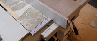
- For small production volumes, it is best to do this on a circular machine.
- First you need to measure the depth of the groove, which will correspond to the length of the tenon.
- We measure the resulting value on our workpiece. The length of the tenon will be determined by the difference between the width of the workpiece and the length of the groove, the height of the workpiece and the width of the groove, divided in half. The resulting material residues should be removed to obtain a spike.
- After this, you should set the size on the machine equal to the length of the groove, taking into account its width. The circular saw should be fixed at a level equal to ½ the difference between the width of the workpiece and the length of the groove from the tabletop line. Make a couple of cuts along the length of the tenon.
- We fix the saw blade at a height equal to ½ of the difference in the heights of the workpiece and the width of the groove from the tabletop line. Two cuts are made from the end of the workpiece.
- Let's start sawing. To do this, it is necessary to fix the circular saw to the length of the tenon, and the distance from the disk to the stop should correspond to a value equal to ½ of the difference in the width of the workpiece and the length of the groove. We make two cuts along the width of the product on both sides.
- We adjust the distance from the cutting disc to the stop. It should be equal to a value equal to ½ of the difference between the heights of the workpiece and the width of the groove. We make two slits. We round off the edges of the resulting tenon with a carpenter's knife and sand it with sandpaper.
Tenon cutter for router
Tenoning templates come in a variety of configurations. They serve to facilitate the work of cutting joints such as tongue and groove, as well as to speed up the work. With their help, you can make frames, box joints, and cut out various joints for furniture.
The size of the groove, as well as the evenness of its edges, will depend on the shape of the template tooth. To make a tenon cutter with your own hands, you will need guides, with the help of which you will mill the tenons. They should be mounted on two opposite sides of the housing in a checkerboard pattern, located equidistantly.
If these conditions are met, they will fit together perfectly.
Dovetail wood cutter
They are most often used in conjunction with milling machines and machines for making grooves in products made of hard and soft wood. Manufactured from monolithic hard alloys.
Designed to work in conjunction with cylindrical cutters.
How to choose a groove with a router
When performing this work, you need to know that the technique will directly depend on the location and size of the groove. If it is open, then your tool is attached to the tabletop, and the workpiece is guided along the cutter. Accuracy will depend on the position of the plank and the height of the cutter.
To avoid mistakes during the sampling process, always make a test run on scrap wood. Sampling should be done in stages, several passes must be made. After each pass of the cutting part of the router, to prevent it from overheating, it is necessary to remove waste from the working surface of the tabletop.
This can be done using a template cut out of plywood, which should be followed by a cutter with an upper bearing.
We hope that the information obtained from reading this article will be useful to you and useful for use in the household.
Areas of application
In addition to being used in carpentry and furniture production, such a machine can be used for processing wooden and particle boards, for processing floor boards, for finishing doorways and window frames, and for making parquet. Units designed for splicing wooden parts are included in a separate category.
Popular models and manufacturers of wood tenoning machines
One of the most famous manufacturers of woodworking equipment is Japanese. For small productions, the company supplies a compact tenon cutter with program control “Makita 5500 S”. The unit has two engines operating on two pairs of saw blades. The parameters of the device make it possible to obtain a given cutting cleanliness and penetration speed. It can work with wood parts of almost any length.
The Chinese company LTT presents the MXB3515C hydropneumatic tenoning machine on the Russian market. This powerful unit processes the ends of the bars, cuts toothed tenons, and automatically applies glue for reliable splicing of knots. The model has a carriage with a hydropneumatic drive and is intended for work in enterprises producing high-quality joinery, laminated wood panels for the manufacture of furniture, and construction timber.