Preparation of the project description
3) Assessment and self-assessment of the project
4) Protection of the project
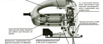
A47: Each machine consists of three mechanisms:
- Motor, cutting mechanism, transmission mechanism
- Motor, transmission mechanism, actuator
- Motor, transmission mechanism, rotating mechanism
A48: What tools are used to control the quality of the manufactured product:
- Jigsaw, center punch, scriber
Scale for measuring whole fractions of a millimeter
A56: What is not an electrical installation tool:
- Pliers
- Wire cutters
- Screwdriver
- Metal scissors
A57: There are no hinges and locks:
- Mortgages
- door
- Invoices
- Mortise
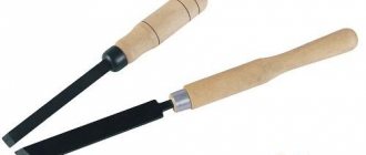
A58: The tailstock of a woodworking lathe is used for:
- Fastening the left end of the workpiece
- Fastening the right end of the workpiece
- Tool mounts
A59: Product finishing is:
- Intermediate operation in the manufacture of a product
- The final operation in the manufacture of a product
- No such operation
A60: Property not related to metals:
- strength
For cutting external threads
A40:
What is called design documentation: 1) List of documents required for the manufacture of the product
2) A set of graphic and text documents that set out all the information about the design of the product
3) List of materials required for the manufacture of products
4) Instructions for use of product
A41: Processing defects are not:
- knot
Strengthening and restoring connections
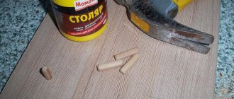
In cases where tenon joints are weakened, but disassembling the frame is impossible or undesirable, adhesive joints are strengthened by injecting fresh glue and holding the structure in a clamped state until the glue is completely cured. If it is necessary to ensure high strength of connections, the structure is strengthened with additional parts. Gussets - plywood plates - are installed inside the frame so that they are not visible from the outside. Wooden bosses are placed inside the drawer belt of chairs and armchairs. Wooden nails - pins are inserted into holes pre-drilled in places of tenon joints.
Disassembled tenon joints are cleaned of old glue with a stiff hair brush, dry or by wetting with warm water. After drying and eliminating other defects on the parts (cracks, chips, etc.), the tenon joints are glued together again. In this case, loose joints are strengthened by increasing the width of the tenon with veneer inserts or wedges made from the material of the part. If the tenon has cracks, they are sawed through with a thin saw (jigsaw) and wedges are inserted with glue. If the tenon is destroyed, it is cut down, drilled out or a socket is hollowed out, and a new tenon dowel is inserted with glue.
Methods of strengthening furniture structures : a - using scarves; b - using bosses
When replacing a box tenon, a recess is made on the inside of the board, equal in width to the size of the tenon, and in depth - half the thickness of the board. An L-shaped block made of the same type of wood with the same direction of the fibers is fitted into it. When replacing a frame straight tenon, a straight insert tenon is made. There are cases when a straight frame tenon, for one reason or another, has tears in the wood, thereby violating its integrity. To restore the operation of the tenon and its integrity, the places where the wood has been torn out are cleaned, giving them a rectangular shape, and wooden inlays are prepared that match the direction of the fibers and correspond in size to the missing parts of the tenon. After connecting an incomplete tenon with an eye (of course, with glue), the prepared tabs are also driven with glue into their intended nests, formed by the walls of the eye and the preserved working part of the tenon.
On stools and chairs, the tenons of the front legs sometimes break because they are located too low and because of this are accessible for standing on them with your feet, for which they, of course, are not intended. If you have the right material, the easiest way is to replace the broken part with a new one. But if such a breakdown occurs in furniture made of red, walnut or other valuable or rare wood, then the material may not be immediately found. In this case, you need to make a new insert tenon. Usually the prong can be removed by loosening the surviving spike in its socket and without destroying the remaining connections.
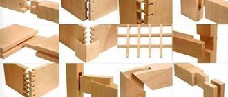
Repair of disassembled tenon joints :
a, b - strengthening tenon joints with wedge and straight inserts, c - replacing a broken box awl with an L-shaped insert; d - replacing the frame corner tenon with a rectangular dowel (dowel); d - connection of the chair leg to an oblique reveal, f - the same to a plug-in tenon; g - strengthening the tenon by widening the bottom of the socket and bending the knot while driving wedge inserts into the cuts
The insert tenon can be made as follows. The hole is cut with a hacksaw, and then a socket 50-60 mm deep is selected with a chisel. The width of the tenon will be 5-8 mm less than the width of the leg, it will be like a “half-darkness”, since it can only be seen in the finished repaired chair from below, if you turn the chair upside down.
Then an insert of the appropriate size is cut out (there is no need to plan it). Any wood is suitable for insertion. The upper part of the eyelet in the chair leg is glued with a wooden block tenon thick and 5-8 mm wide. After this, assembly is carried out using glue: first, the prong is hammered into the eye with the remaining tenon, then the insert is hammered into the second eye, cleared of old glue, and the prong with a groove is placed on top of it. At this point it is compressed with a clamp so that the connection with the glue is as strong as possible. Please note that you can no longer stand on this leg with your feet; its role is purely constructive and partly decorative.
If the material of the same type of wood is available, then it is better to replace the leg completely, making it in two parts. A new spiked leg is sawn at an acute angle with a fine-toothed hacksaw, and after installation in place, it is glued and clamped in a clamp. In this case, the length of the bar for the cutting should be greater than the width of the cut. There is no need to clean the joints between the parts of the leg before gluing. To prevent the oblique cuts from slipping during pressing, the joint can be temporarily fixed with nails driven into the leg from the inside. The holes remaining after the nails can be sealed with plugs made from the same wood or simply filled with sawdust and glue. This method is called, as you already know, an oblique fugue connection.
Chair legs that have cracked at the eyelets are glued together and additionally reinforced with short dowels. The pins are driven with glue into holes drilled from the inside of the bars, but not through them.
It often happens that a recently purchased chair begins to become loose, and the spikes of its parts easily come out of their eyes. Of course, this is a manufacturing defect associated with the manufacture of parts from wood with high humidity, which led to their excessive shrinkage during drying; it could also be the negligence of the carpenter who did not properly coat the tenons and lugs with glue, or did it with very thick glue that did not properly saturate the wood. This may also be due to inaccuracy in the machine production of the eyes and the filing of the tenons (tolerances are not met).
To eliminate a defect, you need to eliminate the root cause leading to this defect. And to do this, you need to disassemble the chair without putting much effort into it, without, however, disassembling the strong components. Those nodes where the spikes easily come out of their sockets should be strengthened in a fairly simple way. The nest of the loosened unit is expanded from bottom to top with a chisel by 2-3 mm in both directions so that as a result it becomes not rectangular, but trapezoidal. After this, at the end of the tenon of the leg or drawer along its entire length, you need to make one or two cuts with a hacksaw, where one or two wedges, respectively, with a width equal to the thickness of the tenon and a thickness of up to 3 mm, are inserted onto the glue. The wedges are inserted so that they protrude from the plane of the tenon end by 6-8 mm. After this, the socket and tenon are smeared with glue, the tenon is inserted into the socket and driven until it stops using a hammer (or better yet, a mallet). While driving the tenon all the way, the wedges will also enter the cuts all the way, pushing its end apart and tightly filling the widened socket, as a result of which the knot will become quite durable in use.
A tongue-and-groove connection, if it has weakened as a result of shrinkage of the tongue in thickness, is sealed by gluing strips of veneer to the tongue on both sides. If the ridge is cracked or broken, it is cut down and a tongue of the same width and depth as the board being attached is made in its place. At the same time, the boards are joined onto a lath made of the same type.
The joints of the boards into a smooth fugue, weakened as a result of warping of the boards or shrinkage, are strengthened by cross-cutting them with dowels of a trapezoidal or rectangular cross-section, which are inserted into grooves made on the inner (non-facial) side of the part. The width of the groove and key is 20-30 mm, thickness - about 10 mm (for thin boards - at least half their thickness). Glue the boards along the edges and glue the dowels at the same time. To do this, after applying the glue, the boards are placed face down on a dense and even backing board, the dowels are inserted and placed under the press. At the same time, the boards are compressed from the sides with clamps. This also eliminates minor warping.
Strengthening connections to the ugly puffer :
a - trapezoidal and rectangular keys; b - sealing the joint with sliced veneer plates; c - inserted spikes (butterfly)
The traditional method is to strengthen joints on a smooth fugue with inserts in the form of a double tenon “dovetail” (or, as it is also called, “butterfly”) with a constriction along the rafting line of the boards.
Similar articles:
- Tenon joints
- Corner tenon joints - group A - subgroup 4
- Transverse T-joints - group B
Corner tenon joints - group A - subgroup 2- Corner tenon joints - group A - subgroup 1
- Corner tenon joints - group A - subgroup 3
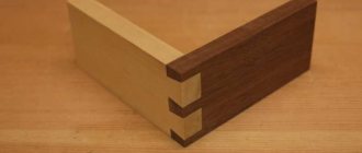
Joinery tenon joints
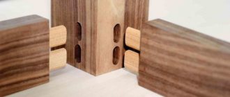
In the production of joinery, the main type of joint is tenon, consisting of two elements: a tenon and a socket or eye.
The pieces of joinery are connected to each other by a tenon joint, consisting of two elements - a tenon and a socket , or eye .
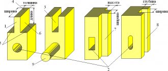
A tenon is a protrusion at the end of a bar that fits into the corresponding socket or eye of another bar. The spikes can be single (Fig. 47, a), double (Fig. 47, b), multiple (Fig. 47, c), i.e. more than two.
A solid tenon is a tenon that is integral with the bar. An insert tenon is a tenon made separately from the bar.
The tenon is made from a separate piece of wood of the same species as the bars being joined, or from more durable wood. In both cases, the direction of the fibers of the tenon wood should be proportional.
A tenon with a cross-section in the form of a circle is called round (Fig. 47, d).
The dovetail tenon (Fig. 47, e) has a profile in the form of an isosceles trapezoid with a large base on the end face of the type; one-sided dovetail tenon - in the form of a rectangular trapezoid on the end face of the tenon (Fig. 47, e).
The serrated tenon has a profile in the form of a triangle or trapezoid, the smaller base of which is the end face of the tenon (Fig. 47, g), the double-oblique toothed tenon (Fig. 47, h) is an isosceles triangle.
Single and double tenons are used in the manufacture of windows, frame doors, and furniture; dovetail spike - in the manufacture of drawers and boxes; jagged tenons - for adhesive joining of parts (splicing) along the length.
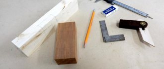
In order to form a tenon, an eye, a socket, the processed bars, planed on four sides to the required size, are pre-marked (Fig. 47, i, j, l, m).
Rice. 47. Types of spikes: a – single; b – double: c – multiple; g – round; d – “dovetail”; e – one-sided “dovetail”; g, h – jagged; and – nest; k, l – eyes; m – blind thorn; n - thorn in the dark; o - thorn in semi-darkness.
Spikes in the dark (Fig. 47, n) and semi-dark (Fig. 47, o) are used in the manufacture of frames, furniture, etc.
A tenon in the dark is made not only at the end connection, but also in cases where it is required that the edges of the nest are invisible , since it is not always possible to obtain smooth edges of the nest. To hide this defect, darkness , i.e. remove part of the tenon along the width from one or both sides.
The spikes are flat , round , rectangular and trapezoidal .
A tenon that passes through a block is called through . A thorn that does not pass through is called hidden .
A spike, the side edges of which widen towards the end, is called a “swallowtail” or “nagrat” . If only one side edge of a tenon expands, it is called a one-sided “burst.”
The side edges of the spine are called cheeks ; the cut end parts of the bar, forming a tenon, are shoulders ; the end part of the tenon is the end . The length of the tenon is the distance from the shoulder to its end (end), the width is the transverse size of the cheek, the thickness is the size between the shoulders of the tenon (Fig. 11).
Rice. 11. Elements of a tenon connection: 1 - tenon; 2 - shoulders; 3 - cheeks; 4 - eye; 5 - nest.
The types of tenon joints, depending on the thickness of the parts being connected, are given in table.
Table
Joinery tenon joints
The tenon connection must be made with interference and clearance values in the range of 0.1–0.3 mm, i.e., almost tight.
The main disadvantages in a tenon joint are: inconsistent dimensions of the tenon in length, thickness, non-parallelism of the surfaces of the tenon or eye, chips, tears, leaks in the tenon joint, etc.
The strength of a tenon joint largely depends on the correct choice of tenon sizes.
The main dimensions of the studs are determined by GOST 9330.
So,
— thickness of a single spike S = 0.4 S0;
— thickness of the double spike S1 = S3 = 0.2 S0;
— triple S1 = S3 = 0.14 S0,
where S0 is the thickness of the part (Fig. 12).
The calculated thickness is rounded to the nearest larger nominal size: 6, 8, 10, 12, 16, 20 and 25 mm.
The length of the through tenon should be equal to the width of the bar, the length of the blind tenon should be half the width of the bar.
The depth of the socket is made 2-3 mm greater than the length of the spike.
It is recommended to bevel the end faces of the tenon on both sides at an angle of 25-30 ° so that the tenon fits better into the socket and the glue is less likely to run off the cheeks of the tenon.
In double and triple tenons, the gluing area increases by 2-3 times and the strength of the connection increases.
The dovetail tenon is strongest at an angle of 10° . At a larger angle, the cheeks of the tenon chip off, and the connection becomes less strong.
Making spikes and lugs
When making tenons and eyes, the following operations are performed: mark the tenons and eyes, saw down, cut out the shoulders and hollow out the eyes. In accordance with the working drawing, the dimensions of the connections are determined, after which they begin marking.
The marking of the corner end connection on the open through single tenon UK-1 for bars 42 mm thick and 65 mm wide is shown in Fig. 56. For compound UK-1 Sl = 0.4S0; S2 = 0.5(S0 – S1), where S0 is the thickness of the block, equal to 42 mm. Hence the thickness of the tenon S1 = 0.4 S0 = 0.4 42 = 16.8 mm (rounded to equal 16 mm), S2 = 0.5 (42 – 16) = 13 mm. In accordance with these data, the spikes are marked. Both tenons and eyes can be marked using templates, which are used to mark the ends of the bar.
Rice. 56. Marking of studs and lugs: a – marking of the linear height of the stud; b – marking the length of the tenon with a square and a pencil; c – marking the thickness of the tenon with a ruler; d – applying the mark with a surface planer; d – marking of the end connection; e – eye; g – thorn; 1 – risk; 2 – cut line; 3 – marking line; 4 – shoulder; 5 – part of wood to be removed
The tenons and lugs are sawed down a bow saw very carefully, since a distortion of the tenon will lead to a distortion of the sash. If the tenon is thicker than the design size, then when seated in the eye it can split the block, and if it is thinner, the connection will be weak, since it will not fit tightly.
When sawing, make sure that the saw passes near the mark; only in this case will you get the exact size of the tenon or eye. When making tenons, the marks are sawed only from the outside, and when making eyes - from the inside.
When starting sawing, to quickly deepen the saw, place the saw on the edge at an angle of 15–20° and, after making several movements towards yourself, deepen the saw without pressure, after which they saw evenly without pressure or jerking. After washing, the hangers are cut off. After cutting, the eyelet is hollowed out with a chisel and mallet and cleaned with a chisel.
Figure - Scheme of marking and processing of tenon joint elements
Depending on the thickness of the products and the required strength, the bars are connected with one, two or more tenons. Increasing the number of spikes increases the bonding area.
The tenon joints of the bars are angular end, middle and box.
The angular end connections of the bars are made with tenons: open end-to-end single UK-1.
Figure - Dimensions of the open end-to-end single end connection of UK-1 bars
Open end-to-end double UK-2
Figure - Dimensions of the open end-to-end double end connection of bars UK-2
Open end-to-end triple UK-3
Figure - Dimensions of the open end-to-end triple end connection of UK-3 bars
Non-through with semi-darkness UK-4
Figure - Dimensions of a closed blind corner end connection of bars with semi-darkness UK-4
Through with semi-darkness UK-5
Figure - Dimensions of the open end-to-end corner connection of bars with semi-darkness UK-5
Not through with darkness UK-6
Figure - Dimensions of the non-through corner end connection of the bars with darkness UK-6
Through the darkness UK-7
Figure - Dimensions of the through corner end connection of the bars with darkness UK-7
(dowels) are increasingly being used . The main advantage of joints on such spikes is the simplicity and strength of corner ties. The use of dowels makes it possible to mechanize and automate production processes.
The strength of the dowel connection depends on the following factors: the amount of interference (clearance) in the connection; the depth of pressing of the dowel into the end of the bar and into the edge of the paired bar (for example, connecting the drawer of a chair with the leg); method of applying glue: only on the walls of the hole or dowel or on both surfaces to be connected; the type of wood from which the dowel is made; dowel diameter.
According to GOST 9330, the total length of the dowel is L = 2.5-6d, where d is the diameter of the dowel .
Non-through and through round insert tenons UK-8
Figure - Dimensions of the non-through corner end connection of the bars on the round insert tenons UK-8
On the “mustache” with an insertable non-through round tenon UK-9
Figure - Dimensions of the non-through angular end connection of the bars on the miter with plug-in round plug-in tenons UK-9
On the “mustache” with an insertable non-through flat tenon UK-10
Figure - Dimensions of the non-through angular end connection of the bars on the “mustache” with the insertion non-through flat tenon UK-10
On the "mustache" with an inserted through flat tenon UK-11
Figure - Dimensions of the angular end connection of the bars on the "mustache" with an inserted through flat tenon UK-10
The dimensions of tenons and other elements of corner end tenon joints are given in Table 5.
Table 5
Dimensions of tenons and other elements of corner end connections