Skate
The skate can be made in a variety of ways. The main requirement for it is the absence of significant deflection under the influence of vertical loads, otherwise a horizontal expansion of the rafters will appear.
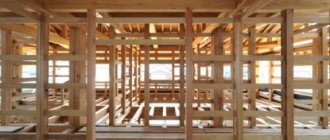
Bearing wall
If there is a load-bearing wall in the center of the house, it can be used to absorb and transmit loads from the ridge. The ridge can be a mauerlat mounted on top of the wall, or a horizontally laid board with a cross-section of at least 38×140 laid on vertical posts with a cross-section of at least 38×89, installed in increments of no more than 1.2 m.
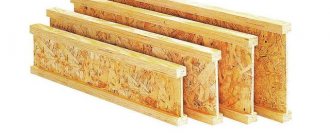
Ridge beams
As a load-bearing ridge, you can use ridge beams made of various materials and having different designs. It is necessary to take into account that the subsidence of the ridge under a vertical load in the rafter system under consideration inevitably leads to the emergence of horizontal thrust forces at the ends of the rafters. At the same time, the maximum amount of movement of the ends of the rafters is limited and linearly depends on the ridge subsidence, which makes it possible to take it into account when designing.
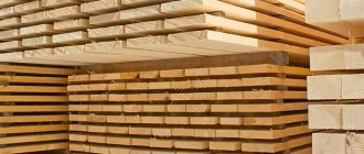
The simplest to design and calculate are ridge beams made from three or more fused boards. To make ridge beams for large spans, it is possible to use LVL beams and flat trusses.
In the previous article “Calculation of the rafter system” we talked about the loads that need to be calculated so that the installation of the roof rafter system does not turn into a big problem during the operation of the house. In particular, we promised to give an approximate calculation of the total loads acting on the roof.
Ridge beam extension
To carry out further work you will need the following tools:
- saw (if the lumber you choose has a significant thickness, then it is wiser to use electric or gas-powered tools);
- electric plane;
- perforator;
- hammer;
- building level and plumb line.
The roofing plate is installed using anchor bolts.
Sometimes the beam needs to be increased, since the standard 6 m is not enough for the roof ridge. It is more convenient to carry out this procedure directly at the construction site, because the extended structure can be quite difficult to transport to the roof.
The place where the beam fastening seam will go must be selected so that it lies on the ceiling (for example, a wall). Remember that a long beam needs additional support.
To provide vertical support, a sufficiently thick board is taken, to which 2 pieces of timber are attached to the sides. As a result, you should have an open frame in which the bars will serve as vertical supports for the beam. The junction of 2 bars on the ridge should be on this frame.
The sections of timber that will form the ridge are fastened together with sufficiently long (at least 2 m) boards. To do this, the ends of the beam are laid in the place provided for them, their correct location is checked using a level and they are sewn together with boards on the sides. With this method of fastening, the dimensions of the ridge beam are unimportant. The whole structure turns out to be quite reliable.
Approximate calculation of total roof loads
Let's assume that we are building a house in the Vladimir region. The house has a gable roof with a slope of 45° and an attic room. The total height of the building is 10 m. The roof of the house is made of metal tiles. The attic will be covered with plasterboard, 1.25 cm thick and insulated with URSA glass wool 0.18 m thick. We look at the zoning map for snow load given in SNiP 2.01.07-85. To calculate the load for complete destruction for the Vladimir region, the pressure of the snow cover must be taken equal to 180 kg/m², and for maximum deflection - 126 kg/m². The coefficient m for slope angles equal to 45° is 0.5. Using maps of the average monthly temperature in January and the average wind speed in winter, we obtain the value of coefficient C=1.
- Q1 (strength) = 180 kg/m² x 0.5 x 1 = 90 kg/m²;
- Q2 (maximum deflection) = 0.7 x 180 kg/m² x 0.5 x 1 = 63 kg/m².
The construction of a mansard roof truss system without calculating the wind load is impossible, therefore, we turn to SNiP 2.01.07-85 maps and determine that the wind pressure on the roof W0 = 32 kg/m², coefficient k = 0.65 for a house 10 m high Vladimir region. We do not know what the wind rose is in a given area, so we take the reduction factor C equal to 1. Thus, W = 32 kg/m² x 0.65 x 1 = 20.8 kg/m²
Diving into the dark waters...roof pie
I can foresee the cries of “it’s not right to do this” from those who are used to doing everything according to a template, like “my grandfather did it, my dad did it, and I will do it.” But I like to do things my own way, and as they say, “use your head, you’re not a robot to act automatically.” The trick is that many people, having adopted some kind of template solution, use it everywhere - somewhere it is really needed, and somewhere it is needed like a mare’s fifth leg. But ours are 1.5 kg. Gray matter consumes too much energy (scientists have proven that even more than all other functions of our body), so laziness turns it on at full capacity. And yet, as a programmer, I have to do this regularly.
Having studied the principle of operation of the differential. membranes and (hydro-windproof vapor-permeable films), their types and properties (vapor permeability coefficient, what column of water can withstand, tensile strength, at what angle of the roof condensate drops begin to roll, etc.), as well as visualizing all processes in the head condensation formation, air movement, under the specific design conditions of my house, as well as climatic conditions. I decided to choose a diff. a membrane whose roll-off of condensate droplets is not very good at my roof angle (I’ll explain why below), and I abandoned the counter-lattice (oh God, what a sin).
Here are the conditions that need to be taken into account and the arguments:
- Winters are not cold; temperatures rarely drop below zero. By the way, in my shed, where I have been living for three years now, the insulation thickness is only 10 cm, there is some kind of film on top, you can even hear it dangling during strong winds, but condensation has never dripped from the ceiling. And with a total insulation thickness of 20 cm, in my house, the dew point will most likely be somewhere in the middle of the insulation, and streams will certainly not flow.
- Let me remind you that the width of the rafters is 20 cm, but between them there will be not all 20 cm of insulation, but only 15 cm (the remaining 5 cm will be added by additional lathing from below, on which coniferous lining or drywall will also be placed, I haven’t decided yet) . Those. it turns out from the top of the insulation to the membrane - 5 cm, which is quite enough to blow through and evaporate condensation from the surface of the insulation, if it forms. So that there is an air flow from bottom to top, i.e. towards the ridge, provided a ventilation gap downwards. It is not very big so that there is no direct wind, but it is moderate.
- another 5 cm of air space from the top of the film to the corrugated sheet , but here the air flow from below is slowed down by the sheathing (although not 100%, because there is still a small gap between the membrane and the sheathing, even though I stapled it in place) , and as you know, the breeze doesn’t move much horizontally. But it will still be present, just remember why they make vents in the basement ! If this theme didn't work, they wouldn't be made. And even if we hypothetically assume that there is no horizontal movement of air flows at all, then we still have air space in the wave of the roof itself , which is not flat.
- If suddenly a few drops of condensation form (which is unlikely, see the conditions below), then without flowing down to the sheathing, I am sure they will evaporate normally without forming puddles near the first sheathing bar that comes across. Well, I’m 99% sure of this, no matter what.
I stapled the membrane with normal tension. Later, when I was jumping on the crate, I stepped on it unsuccessfully and fell through. Unfortunately, it was not strong enough to withstand my already light weight. So we had to patch it up. Using a stapler along with sewing with nylon threads to prevent them from rotting.
The nuances of choosing and laying a purlin
To calculate the cross-section of the ridge girder, it is necessary to sum up the loads from half the roof, or rather, from its horizontal projection. The dimensions of the run depend on its length and the dimensions of the building. In a large building, the purlin will be so powerful and heavy that installation will require the use of a crane. However, it is very difficult to find an even, solid beam longer than 6 meters, so to make such a ridge it is better to take an ordinary log or a laminated beam.
In this case, the ends of the ridge element, which will rest on the wall and are actually walled up in it, must be treated with antiseptics and wrapped in roofing felt or roofing felt to protect it from rotting. If an all-wood beam is used, then its end must be cut at an angle of 60 degrees and left open, that is, this end should not come into contact with the wall material. This measure is needed in order to increase the area of the end, which will improve moisture exchange in the wood.
How to calculate the length?
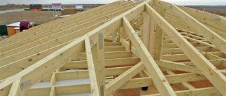
This size of the ridge girder is also directly related to the angle of the roof . To determine the length of the top beam of the hip roof rafter frame, you need to draw a section of the hip roof along the axis of the ridge.
The drawing will produce a trapezoid, the top side of which is the ridge itself, and the base is the width of the facade wall. The lower angles are equal to the calculated roof slope angle.
If you lower perpendiculars from the vertices of the figure to the base, you get two rectangles, where the opposite leg to the angle of inclination “A” is the height of the roof Hk. By multiplying the height by tg “A”, we get two segments that need to be subtracted from the length of the base of the trapezoid. The resulting segment will be equal to the length of the skate.
Reference. To determine the design parameters of the hip roof rafter frame, including the ridge, you can contact one of the online services. On the Internet, select a calculator and fill in the service windows with the initial data. The output is the desired values.
Section calculation
To select the cross-section of a ridge beam, it is necessary to carry out a calculation based on two indicators:
- for deflection;
- and calculate the fracture strength.
To calculate the ridge girder for deflection and strength, you must use the following formulas:
- First, you need to determine the internal stress that occurs in the beam when bending under the influence of an external load. This value should not be greater than the calculated bending resistance of the material, which can be found in the table or in SNiP number II-25-80. We find the internal stress using the formula: Σ = M:W, where:
- Σ is the desired value, which is determined in kg per cm²;
- M – maximum bending moment (kg X m);
- W is the moment of resistance to deflection at the selected rafter section (found by the formula bh²: 6).
- The deflection of the purlin must be compared with the normalized value, which is equal to L/200. He should not exceed it. The deflection of the beam is found by the formula f = 5qL³L:384EJ, where:
- J is the moment of inertia, which is determined by the formula bh³:12, where h and b are the dimensions of the purlin section;
- E – the value of the elastic modulus (for coniferous wood it is equal to 100 thousand kg/cm²).
First you need to calculate the bending moment. If there are several of them on the beam diagram, then after the calculation the largest one is selected. Next, to determine the dimensions of the beam section, we can arbitrarily set the beam width parameter and then determine its required height using the formula: h = √¯(6W:b), where:
- b is the beam width we set in cm;
- W is the bending resistance of the run, the value is determined by the formula: W = M/130, where M is the largest bending moment.
You can do the opposite, set an arbitrary width of the purlin and calculate its height using the formula b = 6W:h². After you calculate the dimensions of the purlin section, it must be checked for deflection using the formula from point 2.
Attention! It is better to include a small margin of safety in the calculated deflection value.
When the ridge beam is designed for deflection, it is necessary to compare this value with the value L:200. If the deflection in the longest section does not exceed this value, then the section of the beam is left as it turned out. Otherwise, it is necessary to increase the height of the run or use additional supports from below. In the latter case, the resulting section must be double-checked by again performing the calculation taking into account the supports used.
The resulting values for the width and height of the ridge must be rounded up. In principle, this calculation is not difficult to perform. The most important thing is to indicate the values in the required units of measurement, that is, do not get confused when converting meters to centimeters and back.
The procedure for splicing rafters
In the construction business, there are several ways to join timber together lengthwise. The choice of splicing technique is influenced by the distance between the rafters and the available fastening and building materials.
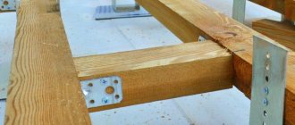
The fastest way to connect timber and thus increase their length is joining.
To join, the ends of both boards or beams must be cut at an angle of 90 degrees.
The ends must fit very precisely against each other - this will ensure maximum strength of the rafters after splicing.
On both sides of the joint, wooden strips are placed on the lumber and secured with nails, driving in the fasteners in a diagonal order.
Instead of wooden overlays, you can use metal plates with pre-drilled holes in them in a checkerboard pattern.
The next method that can be used to splice rafters is the oblique cutting method. This method is mainly used for joining square lumber.
The ends of the two beams must be cut at an angle of 45 degrees. The length of the cut should be twice the width of the beam.
Sharp corners on both parts are ground at an angle of 90 degrees, the depth of the resulting areas should be 15% of the height of the section. The platforms are made similarly at the other end of the oblique cut.
Having connected both elements, secure the joint with a bolt, screwing it into the middle of the joint. The round opening for the bolt has to be made in advance.
In this case, it is important that the diameter of the hole is equal to the diameter of the fastener or is slightly smaller - then there will be no backlash, and the bolt will hold firmly in the rafter.
The easiest way to join lamellas is to use the overlap method. Here, the carpenter does not require special precision and skill, since the boards are connected with an overlap of 100 cm.
Nails are driven in in a chaotic manner over the entire overlap area. Bolts and studs are sometimes used instead of nails.
When using such fasteners, you have to pre-drill holes in the boards, but the use of bolts and studs instead of nails increases the reliability of the structure.
When splicing rafters, we must not forget that the connection point should be in the least loaded area of the rafter structure.
Joint lumber cannot be used for installation as diagonal rafters, since this structural element has to withstand increased loads.
At the same time, it should be noted that the strength of legs made from jointed lumber can exceed the strength of solid boards or beams.
With hanging rafters
These are systems in which the rafter legs rest only on the external walls without intermediate supports (load-bearing walls). For gable roofs, the maximum span is 9 meters. When installing a vertical support and a strut system, it can be increased to 14 meters.
The good thing about the hanging type of gable roof rafter system is that in most cases there is no need to install a mauerlat, and this makes the installation of rafter legs easier: there is no need to make cuts, just bevel the boards. To connect the walls and rafters, a lining is used - a wide board, which is attached to studs, nails, bolts, crossbars. With this structure, most of the thrust loads are compensated, the impact on the walls is directed vertically downwards.
Types of rafter systems with hanging rafters for different spans between load-bearing walls
Gable roof rafter system for small houses
There is a cheap version of the rafter system when it is a triangle (photo below). Such a structure is possible if the distance between the external walls is no more than 6 meters. For such a rafter system, you can not make calculations based on the angle of inclination: the ridge must be raised above the tie to a height of at least 1/6 of the span length.
But with this construction, the rafters experience significant bending loads. To compensate for them, either rafters of a larger cross-section are taken or the ridge part is cut in such a way as to partially neutralize them. To give greater rigidity, wooden or metal plates are nailed on both sides at the top, which securely fasten the top of the triangle (also see the picture).
The photo also shows how to extend rafter legs to create a roof overhang. A notch is made, which should extend beyond the line drawn from the inner wall upward. This is necessary to shift the location of the cut and reduce the likelihood of the rafter breaking.
Ridge knot and fastening of rafter legs to the backing board with a simple version of the system
For mansard roofs
Option with installing a crossbar - used when. In this case, it serves as the basis for lining the ceiling of the room below. For reliable operation of a system of this type, the crossbar cut must be hingeless (rigid). The best option is in a semi-frying pan (see picture below). Otherwise, the roof will become unstable to loads.
Please note that in this scheme there is a Mauerlat, and the rafter legs must extend beyond the walls to increase the stability of the structure. To secure them and dock them with the Mauerlat, a notch is made in the form of a triangle. In this case, with an uneven load on the slopes, the roof will be more stable.
With this scheme, almost the entire load falls on the rafters, so they need to be taken with a larger cross-section. Sometimes the raised puff is reinforced with a pendant. This is necessary to prevent it from sagging if it serves as a support for ceiling cladding materials. If the tie is short, it can be secured in the center on both sides with boards nailed to the nails. With a significant load and length, there may be several such belays. In this case, too, boards and nails are enough.
For large houses
If there is a significant distance between the two outer walls, a headstock and struts are installed. This design has high rigidity, since the loads are compensated.
With such a long span (up to 14 meters), it is difficult and expensive to make the tie in one piece, so it is made from two beams. It is connected by a straight or oblique cut (picture below).
For reliable joining, the connection point is reinforced with a steel plate mounted on bolts. Its dimensions must be larger than the dimensions of the notch - the outermost bolts are screwed into solid wood at a distance of at least 5 cm from the edge of the notch.
In order for the circuit to work properly, it is necessary to make the struts correctly. They transfer and distribute part of the load from the rafter legs to the tie and provide structural rigidity. Metal pads are used to strengthen connections
When assembling a gable roof with hanging rafters, the cross-section of lumber is always larger than in systems with layered rafters: there are fewer load transfer points, therefore each element bears a greater load.
Preparatory stage of work
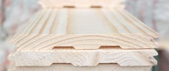
A ridge girder is a horizontal beam that is located in the upper part of the roof at the junction of 2 slopes. Typically, ridge beams are used as a beam. This type of lumber is specially designed for heavy loads. But before purchasing material, it is necessary to calculate the angles of inclination of the roof slopes. It is generally accepted that the smaller this angle, the cheaper it will cost to build a roof. Calculations should be based not on economic benefits, but on technical characteristics. It is necessary to take into account the load on the rafters and the estimated weight of precipitation (especially in winter). That is why in central Russia the fastening of the rafters is positioned so that the slopes are located at an angle of 45°. This type of roofing is considered optimal.
Next, you should select the required building material. A truly reliable roof can only be provided by a lightweight but sufficiently strong structure. Therefore, it is wiser to opt for lumber made from pine. For the roof frame, a board is usually used, the dimensions of which do not exceed 20x5x600 cm. In addition, it is necessary to purchase a ridge beam with a section of 20x20 cm.
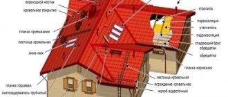
Figure 1. Roof ridge diagram.
When choosing materials, it is necessary to consider not only their size. You need to pay attention to quality. Never buy unseasoned lumber.
After some time, the fastening of the rafters, assembled from such boards, will certainly fail. Accordingly, the entire roof is deformed. Remember that wood is considered ideal if its moisture content does not exceed 20%.
Return to contents
System for houses with two internal load-bearing walls
If the house has two load-bearing walls, install two rafter beams, which are located above each of the walls. The beams are laid on the intermediate load-bearing walls, the load from the rafter beams is transferred to the beams through the racks.
In these systems, a ridge run is not installed: it provides expansion forces. The rafters in the upper part are connected to one another (cut and joined without gaps), the joints are reinforced with steel or wooden plates, which are nailed.
In the upper non-thrust system, the pushing force is neutralized by the tightening. Please note that the tightening is placed under the purlin. Then it works effectively (top diagram in the figure). Stability can be provided by racks, or joints - beams installed diagonally. In the spacer system (in the picture it is below) the crossbar is a crossbar. It is installed above the purlin.
There is a version of the system with racks, but without rafter beams. Then a stand is nailed to each rafter leg, the other end of which rests on the intermediate load-bearing wall.
Fastening the rack and tightening in the rafter system without a rafter purlin
To fasten the racks, 150 mm long nails and 12 mm bolts are used. Dimensions and distances in the figure are indicated in millimeters.
Calculation of ridge beams and purlin dimensions. If you follow the wording, the purlin is a load-bearing beam that rests on the wall at both ends. In most cases, the ridge rests on two pediments, but sometimes this formulation does not entirely correspond to reality. So, in hip roofs the ridge does not rest on the walls. The simplest option is a beam laid on the gables without the use of supports. In any case, it is necessary to correctly determine the cross-section of the ridge girder.
Installation of roof ridge
Before starting work, draw up a diagram for fastening all roof elements. An example of such a scheme is shown in Fig. 1.
Only with the help of such a drawing will you be able to correctly determine the required dimensions and think through the fastening of the rafters, which will be most effective for the selected roofing material.
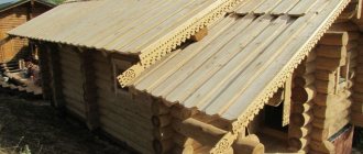
A ridge beam is usually a crossbar located at the top of the roof structure. It is necessary in order to evenly redistribute the pressure of the roof onto the walls of the house. Installing such timber yourself is not the easiest job. And it must be approached with full responsibility.
First of all, you need to calculate the length of the timber you will need. Usually, when building traditional Russian houses, there are small protrusions on the sides of the roof. As a rule, their width does not exceed 1.5 m. The entire structure must be calculated so that the fastening of the ridge beam covers the entire length of the canopies.
Waterproofing is laid on the base of the roof (usually roofing felt is used for it) and the edges of the insulation are folded around the beam. Next, the structure is strengthened with reinforcement. To do this, take 2 rods of 40 cm each and fix them on the sides of the beam. It is wiser not to drill out the beam itself, otherwise cracks may appear on it.
Return to contents
With layered rafters
In gable roofs with layered rafters, the ends rest on the walls, and the middle part rests on load-bearing walls or columns. Some schemes push through the walls, some don't. In any case, the presence of a Mauerlat is mandatory.
Non-thrust schemes and notch units
Houses made of logs or timber do not respond well to thrust loads. For them they are critical: the wall may fall apart. For wooden houses, the rafter system of a gable roof must be non-thrust. Let's talk about the types of such systems in more detail.
The simplest non-thrust rafter system diagram is shown in the photo below. In it, the rafter leg rests on the mauerlat. In this version, it bends without pushing the wall.
Pay attention to the options for attaching the rafter legs to the Mauerlat. In the first, the support area is usually beveled, its length being no more than the section of the beam. The depth of the cut is no more than 0.25 of its height.
The top of the rafter legs is laid on the ridge beam, without fastening it to the opposite rafter. The structure results in two pitched roofs, which in the upper part are adjacent (but not connected) to one another.
The option with rafter legs fastened at the ridge part is much easier to assemble. They almost never push against the walls.
To operate this scheme, the rafter legs at the bottom are attached using a movable connection. To secure the rafter leg to the mauerlat, one nail is driven from above or a flexible steel plate is placed from below. See the photo for options for attaching rafter legs to the ridge girder.
If you plan to use heavy roofing material, it is necessary to increase the load-bearing capacity. This is achieved by increasing the cross-section of the rafter system elements and strengthening the ridge assembly. It is shown in the photo below.
Reinforcing the ridge assembly for heavy roofing material or for significant snow loads
All of the above gable roof schemes are stable in the presence of uniform loads. But in practice this practically never happens. There are two ways to prevent the roof from sliding towards a higher load: by installing a screed at a height of about 2 meters or by struts.
Options for rafter systems with contractions
Installing contractions increases the reliability of the structure. In order for it to work properly, it needs to be secured to them with nails at the places where it intersects with the drains. The cross-section of the timber for the scrum is the same as for the rafters.
They are attached to the rafter legs with bots or nails. Can be installed on one or both sides. See the figure below for attaching the screed to the rafters and ridge girder.
In order for the system to be rigid and not “creep” even under emergency loads, it is enough in this option to ensure rigid fastening of the ridge beam. In the absence of the possibility of its horizontal displacement, the roof will withstand even significant loads.