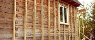
Let's touch on an issue that is not obvious, but extremely important for those who are just planning to build a wooden house or bathhouse - connecting timber in the corners.
In the article we will give a brief overview with diagrams of the popular types of connections used today in mass construction, we will go through the advantages and disadvantages, and most importantly, we will answer the question of which timber connection we consider the best and recommend that clients of SK Smirnov choose.
I’ll say right away that the texts for the blog are written by a person who is directly related to the production of timber and construction - therefore, the evaluative opinion will be based on personal experience.
Secrets of making half-timber frame joints
Half-timber cutting is a simple and reliable way to connect two identical parts at right angles.
This method is useful when creating corner, cross and T-shaped joints. By marking and selecting half the thickness of the material in each part, you will get a neat and durable connection, which will become indispensable when assembling frames and timber structures. Cutting into half a tree is done in different ways: using a router, circular saw or band saw. We'll show you how to create perfectly tight joints using a classic set of hand tools.
TOOLS
What is a warm corner
This is a sealed joint that shrinks evenly. The corner connection of the timber into a warm corner, or tongue and groove, allows you to improve the performance characteristics of the building and ensure the disappearance of “cold bridges” and drafts.
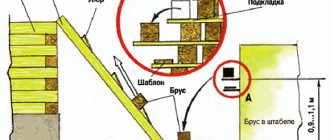
Beam corner connection technology:
- Marking, for accuracy it is better to use a template.
- A groove is made in the lateral plane of one of the crowns, and a tenon is made in the other, completely symmetrical.
- Assembling the walls according to the principle of the first tenon beam on the right, the second on the left.
- Fastening is done with round dowels.
The grooves are made in production conditions using special equipment. You can cut them yourself with a chainsaw, manual machine or jigsaw. In order for the final structure to be durable, it is important to initially use high-quality material with a humidity of no more than 20%. Sealants can be used for additional insulation.
Do-it-yourself half-tree corner joints
Half-timber corner notch (overlapping) is the most common type of frame connection. Its logic is extremely simple: at the ends of both parts, recesses (folds) are cut out along the width of the counter part. The fold forms an edge and a shoulder - they must be perfectly smooth and strictly perpendicular to each other. In a high-quality connection, the surfaces of both parts fit tightly and form a joint without the slightest gap.
Connection marking
Measure the length of the edge along the width of the mating part. Draw marking lines on the edges. Set the thicknesser to half the thickness of the part and make side markings.
Rebate cutting
Using a back saw, saw off the waste part on each part, carefully following the markings without strong pressure or jerking.
Stripping the connection
Using a wide chisel, clean the edge and shoulder, achieving the tightest possible fit of the parts.
Gluing
Before applying glue to the joints of both parts, you should once again check their connection in a “dry state”. If a gap is found in the connection, then some of the parts will have to be replaced: such an error cannot be corrected later. It’s a different matter when you have to apply too much force to connect the parts in a T-shape or cross-shape, or when, with a corner connection, the parts do not fit very tightly to each other.
Then you need to remove the excess with a chisel or clean the surface with sandpaper. At the same time, you should not wield the chisel with excessive zeal. Also make sure that the surfaces do not turn out round. Remember: with any half-tree connection option, the parts must fit tightly to each other.
Clamp carefully
All areas of the joints must be evenly covered with a thin layer of glue. Wait for a while, then connect the parts and check again whether they form a right angle. If everything is in order, clamp the parts with a clamp. Just don’t tighten the screw too tightly, otherwise the glue will “creep” out. The glue must be wiped off immediately, otherwise it will harden on the surface of the part.
https://www.youtube.com/watch?v=y3qdCpEtndI
Before pressing the pieces tightly together, make sure they form a right angle.
T-shaped (T) connection
The lap joint is another variation of the half-timber joint, which is widely used in the creation of frame structures. In this case, the end of one part is adjacent to the middle of the second. A fold is cut out on the first (according to a similar pattern as in a corner joint), and a landing groove is cut on the second. Below is one of the schemes for creating such a groove manually.
Make markings on the front side, focusing on the width of the counter part.
Using a thicknesser and a square, mark the edges.
Make cuts in the waste part. They will facilitate subsequent sampling with a chisel.
Use a wide carpenter's chisel to remove the waste. Remove layers, moving from the center to the edges.
Clean the groove. The edge and shoulders must be perfectly smooth and meet strictly at right angles. This will ensure that the parts fit as tightly as possible.
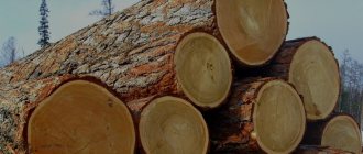
Design features of the log house
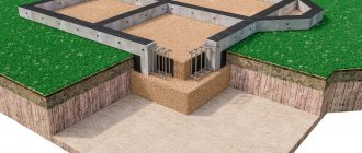
Wooden house-building technologies have their own characteristics associated with the specific qualities of the building material – wood. Shrinkage, shrinkage, exposure to the external environment - these indicators are characteristic only of wooden buildings. Therefore, during construction, special techniques are used, without which logs stacked on top of each other will not form a log house (the basis of a house).
Prepared log a - compensation cut, b - lunar groove
Longitudinal grooves
The log house should be cut in such a way that there are no cracks in the walls. This requires cutting out longitudinal grooves.
The width of the groove depends on the climatic conditions in which the residential building is being built. Winter temperatures reaching 30° below zero are not dangerous if its width is more than 12 centimeters. If the frost reaches 40 degrees and below, the groove should be 14 cm wide.
A semicircular groove, also called a “lunar” groove, is cut along the entire length at the bottom of the log. Since the log is laid on top, rain and snow water cannot penetrate into the inter-crown space.
The radius of the lunar groove affects the quality of fit of the logs: its smaller size (compared to the log itself) allows you to lay a layer of insulation in the resulting space, the protruding edges of which should be protected from moisture. In the case when the diameter of the groove is equal to the diameter of the log, gaps form between the crowns. The fact is that, as a result of uneven shrinkage of the logs, the crowns cannot sit in the right place to make the joint airtight. Such walls require mandatory insulation.
Compensation cut
This design feature protects the logs in the log house from the formation of cracks that appear under the influence of moisture. Wood is a natural material that is very susceptible to its influence.
The task assigned to the compensation (or unloading) cut is to minimize the number of cracks and give the ones that appear a single direction.
Only an experienced specialist can perform cutting, one of the most difficult operations. This is almost jewelry work, since the cut must be made to a certain depth (no more than 1/3 of the diameter) and along the entire length of the log, without touching the locks. If the slightest mistake is made, the cut can become a conductor of cold into the house.
On the issue of fixation
Half-timber joinery joints do not have a mechanical connection, so they are secured using gluing. We discussed in detail how to properly glue wood and choose the appropriate glue in previous materials.
While drying, the structure must be secured with clamps. When placing the clamps, make sure that their pressure is distributed evenly. An incorrectly installed clamp can deform parts or disrupt the fit of the connection.
Unlike frame structures, logs or beams are strengthened using a different technology. In this case, screws, dowels or dowels are used to secure the connection.
Source
How do corners join in modern wooden houses?
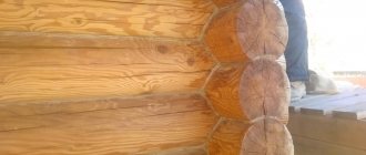
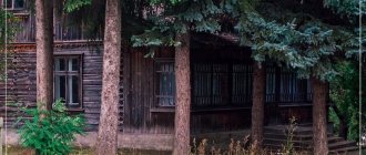
You know, in different ways. Depending on the price segment in which Pestov’s teams work, they don’t think too much and don’t spend time on honing tongue-and-groove technologies - they build end-to-end: quickly and cheaply. Well, yes, the customer will then be tormented by caulking cracks two fingers thick, will go broke on heating and the corners of his house will become covered with mold, but who cares. I wanted it cheap, I got it cheap.
And if you want a visual difference, here are real photos - the butt corner during the assembly of the log house and some time after construction. And this is not the saddest case:
We believe that this option is not suitable for building a house, even a dacha. Avoid teams that will convince you, saying, “We’ve been building this way for ten years and no one has complained.” Believe me, every first one complained.
If we talk about the most popular corner connection, then this is, of course, a warm corner. Well, I mean, the builders present it as warm. In fact, it does not ensure the tightness of the corner and cannot cope with cold bridges. Despite the insulation, profiled timber cannot be made airtight when cut into a “warm” corner. Due to the beveled profile chamfers, through holes are obtained, unfortunately. Those who read to the end will see a video where I show directly on pieces of timber why holes appear.
But let me emphasize that this option is, of course, a thousand times better than simple joining (we use it ourselves, but in combination with drilling):
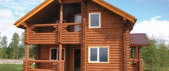
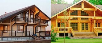
Those companies that work for more demanding clients use more complex units. For example, dovetail. We are just beginning to master this direction, but we can already say - yes, building this way is much more difficult, longer, and more expensive, but the quality cannot be compared with cheaper methods of connecting corners in buildings made of timber. It is this corner that makes sense to be called truly warm.
The secret of the dovetail is that in this corner the slope of the timber cut is made along all planes - it has a cone shape on all sides. Thanks to this, simply under the influence of gravity, the beam clamps on itself, forming a strong, hermetically sealed connection.
One of the most popular corner connections of log houses and baths in the Russian style is assembly into a bowl. As mentioned above, this option is more expensive than dovetail, warm corner and butt. The point is the additional consumption of material for takeouts and the fact that the bowl can only be cut from dry or glued profiled timber. But if you don’t mind the price, then it makes sense to take a closer look at this option (our object is pictured in the photo):
And for those who can afford mansions, the market offers good old-fashioned Canadian hand-cutting. Essentially, this is the same bowl, but made from a powerful log of dead pine (for example). A warm, powerful, beautiful and durable log house that costs a tidy sum of money (our work is also pictured in the photo):
We are building up
There are different ways to connect timber. Since this material has been used for a long time, there are a great many similar types. At the same time, some ancient methods are considered more effective and reliable than their more modern counterparts.
Types of timber connections differ in the principles of execution, place of use, strength and a number of other parameters. For example, it is very often necessary to increase the length of the material used. If the length of the wall or other structure is much greater than the size of the original beam, then it must be increased.
To perform such an operation, the following steps are carried out:
There are many designs of such locks. Each master chooses his own option. The most popular are straight and oblique overhead locks. Such methods have been tested for centuries and are deservedly considered the most reliable. A straight or oblique joint can easily withstand even heavy loads.
Some experts use a half-tree connection. At the connecting ends of the beams, a cut is made up to half their thickness. They are then connected and secured with staples, plates or nails.
But this method of docking is considered not very reliable and durable. The half-tree method is more suitable when joining corners.
Chapter VICuttings
The connections between different pieces of wood are called notches. Basic requirements for the production of cuts:
1) the cutting must be designed in such a way that it resists the forces acting in a given place (compression, tension or shear), taking into account the limits of strong resistance of wood, which are given in Chapter III;
2) the contacting parts of the tree must fit tightly to each other along all planes of the connection, otherwise the distribution of forces will be uneven, which will entail the destruction of parts of the notch;
3) when designing and calculating conventional notches, it is necessary to take into account that all design forces are resisted by the wooden parts of the notch. Those iron fasteners (brackets, bolts, capercaillies, etc.) that are used when cutting conventional systems are intended to resist various random forces in those directions against which the cutting is not designed;
4) in cuttings exposed to precipitation, measures must be taken against stagnation of water, since otherwise this will lead to premature destruction of the tree;
5) cutting should be as simple as possible, which facilitates its accurate execution and control over the quality of execution.
Based on the relative position of the parts, the following main types of connections are distinguished:
1) build-up
– lengthening of logs or beams (piles, racks) in the vertical direction. The forces here are directed along the axis and press the upper of the neighboring parts to the lower;
2) splice
– elongation in the horizontal direction, i.e. here too the axes of the connected parts are located in one straight line.
With regard to the forces acting in these notches, it should be noted that the conditions here are very diverse: either the parts being connected are simply adjacent to one another without transferring forces, or there is a force that stretches the connected parts or, conversely, pressing them together;
3) rallying
– an increase in the width of parts of the tree, i.e., the position of the connected parts when their axes are parallel;
4) mating
— mating at an angle, and the connected parts can be located in a horizontal or vertical plane.
Extension cuts
The easiest way is end-to-end extension
(Fig. 48), with the insertion of a barbed pin to counteract accidental lateral shocks.
Sometimes the pin is replaced with a cast iron shoe (Fig. 48, b
) with an internal partition, against which the ends of the connected parts rest. Such building methods are used when driving piles, and the joint at the end of driving should be at least 2 m below ground level.
Spiked extensions
– single (Fig. 49) and double (Fig. 50) – provides a connection against lateral pushes without the assistance of iron or cast iron fasteners. The width and height of a single tenon are made about ⅓ of the thickness of the timber. It is only necessary to note that the depth of the socket for the tenon should be slightly greater than the height of the tenon, so that the racks touch with their large plane, and do not hang on the tenon. To obtain a double tenon, two mutually perpendicular diameters are divided at the ends and two opposite sectors are cut out to a length of about 2 diameters. The result is a notch that is capable, although to a weak extent, of resisting lateral bending.
Swedish extension method
(Fig. 51) - consists in the fact that the racks connected end-to-end are covered on both sides by overlays, tightened with bolts.
The linings are made 2-3 times the diameter of the rack and are either adjacent to the racks along a plane (Fig. 51, b
), for which the side surfaces of the round racks are cramped, or adjacent to a cylindrical surface (Fig. 51,
a
), for which the linings are taken larger diameter and hollows are selected in them in accordance with the outline of the rack.
Rice. 48. Butt extension: a)
with pin;
b)
with a cast iron shoe.
Rice. 49. Extension with a single spike.
The latter connection is better, since it keeps the upper post from deviating both in the plane of the linings and in the plane perpendicular to it. This type of notch is used in bridges when building piles in abutments, and if paired contractions of the abutment are located at the abutment level, the connection is very reliable.
Rice. 50. Double spike extension.
Rice. 51. Extension using the Swedish method.
Rice. 52. Half-tree extension.
Rice. 53. Building up with the tongue.
Extension of a half-tree invoice
(Fig. 52) is often used when constructing scaffolding. Both ends are cut to half the thickness to a length of 3-3.5 diameters, and to counteract lateral forces, the entire notch is wrapped with hoop iron. For greater reliability of the connection and to counteract bending, sometimes the ends of the posts are cut not at a right angle, but at a sharp angle, according to which a notch is made at the base of the lining, however, this cannot be recommended: if there is the slightest inaccuracy in the cutting of the notch, the pointed end will act like a wedge, splitting the post , and when tilted, half of the stand will break off.
Tongue buildup
(Fig. 53) - a fork is made in one rack into which the thin end of the other rack is inserted. The connection is also wrapped in iron. Due to the weakness of parts of the fork, this cutting is used when constructing temporary scaffolding.
Rice. 54. Butt splicing.
Rice. 56. End butt with ridge.
Rice.
57. Direct overlay.
Butt splicing
(Fig. 54). Both ends are cut at right angles and butted to one another. To avoid moving to the sides, sometimes a bracket is hammered in, the ends of which fit into both beams being connected.
Oblique butt
(Fig. 55) - the cut is made not at a right angle, but along an inclined line extending from the vertical to ¼ of the height of the beam. This allows the ends to be secured with a nail or pin driven in at an angle.
In both cases described, both the staple and the nails serve to resist movement due to accidental lateral shocks.
End butt with tongue
(Fig. 56) - to counteract lateral forces, as well as to avoid a through gap. This notch is used when cutting walls, to connect joined logs, to avoid through blowing.
Straight overlay
(Fig. 57). Unlike the above methods of splicing, when it is required that the parts to be connected lie along the entire line on a support (morts, beds, wall crowns), this notch can rest on a stand supporting the lower protruding end. To ensure this notch does not move the parts to the side, it is sometimes fastened with two bolts. This notch, like those described above, is, of course, not designed for longitudinal tension. The length of the notch is made 1.5-2 times greater than the thickness of the timber.
Rice. 58. Oblique overlay.
Rice. 59. Overlay with an oblique cut.
Rice.
60. Straight overlay with end comb.
Rice. 61. Straight lock.
Oblique overlay
(Fig. 58) is drawn in this way: having set aside 2-2.5 of its thickness from the end of the beam, set aside ¼ of the thickness from the top or bottom edge on the side surfaces, put the same amount away from the end, but on the other side of the beam, and the resulting points (
b
and
c)
connected by a straight line. The overlay is used in the same cases as the straight one, and can also be fastened with bolts or wooden dowels.
Rice. 61, a
.
Straight lock with
tension wedges.
The point of using an oblique overlay instead of a straight one is that if the notch is supported by a post and part of the timber between the posts is subject to load, then at the edge of the post the jointed beam has a thickness not equal to half its thickness, but somewhat more, and further, as it moves away from the post , along with an increase in bending moment, the thickness of the beam also increases.
The use of an overlay with an oblique cut cannot be recommended (Fig. 59), since when bending the parts being connected, chipping may occur at points a and b.
To counteract lateral movements, the ends of the parts connected by the overlay are equipped with end ridges with a width and length of ⅓ of the thickness of the beam (Fig. 60).
When splicing wooden parts subject to tensile forces, a straight and oblique lock is used.
Straight lock
(Fig. 61) is made with a length from 2.5 to 3.5 times the thickness of the beam and is drawn as follows: according to the mark of the length of the lock around the beam, divide its thickness into 8 parts and set aside:
ab
and
a'b'
- ⅜ of the thickness,
b
and
6' e' =
¼ thickness, what remains is
ег = e'г'=
⅜ thickness.
Points b
and
b', e
and
e'
are connected to each other, and in the middle of the length of the castle another line is drawn around the beam, which between these lines will mark the line b -
e;
along this line the ledge of the castle is made.
After this, cuts are made along lines e
-
g
and
b
-
d
and the corresponding parts are chopped off with an ax (see axonometry). The end of the other beam is drawn in exactly the same way. Sometimes this cutting is called a tooth splice.
Straight lock with tension wedges
(Fig. 61,
a
) is done with the aim of tightening the parts of the lock as tightly as possible.
When drawing its line e
–
e
(Fig. 61) is drawn not in the middle of the length of the lock, but at a distance of ⅛ of the thickness from it. The same is done on another beam; therefore, the gap for the wedges is ¼ of the thickness of the timber. There are two wedges for tensioning, and they are hammered in simultaneously from both sides so as not to move the notch to the side.
Diagonal castle
(Fig. 62) is drawn like this.
Having set aside the length of the lock from the end of the beam (2.5-4.5 thicknesses), lay 0.2 of the thickness of the beam on the side edges at the base of the lock and at the end of the beam. The resulting points b
and
c
are connected by a straight line
b
–
c,
which is divided in half, and at the resulting point they are restored to the line
b
–
c
perpendicular
g
–
e,
0.1 thickness is laid off from the point of intersection with the line
b
–
c
Rice. 62. Oblique lock.
Rice. 63. Oblique lock with a spike.
Rice. 64. Straight Dutch lock.
timber in one direction or the other, getting points s
and
and,
the distance between which is equal to 7b of the thickness of the timber.
Points h and i
are connected to
b
and
c,
which outlines the outline of the castle.
The ledge s
-
and
is not drawn perpendicular to the edge of the beam, since then at points
s
and
and
there will be sharp corners that can contribute to the chipping of parts of the lock along the fibers, especially during fitting of the notch. The length of the oblique lock is made longer than the length of the straight lock, since if they were the same length, the plane along which the protruding part of the lock could be chipped would be shorter in the oblique lock than in the straight one.
To counteract lateral forces, an oblique (as well as straight) lock with a spike (Fig. 63) with a width and length of ⅓ of the thickness of the beam is sometimes made. When laying out such a notch, you must first set aside ⅓ of its thickness from the end of the beam to form a tenon and continue marking as indicated.
Wanting to create a splice that can resist not only the forces on the side of the beam, but also prevents the separation of the beams in the vertical direction, sometimes a Dutch lock notch is used (Fig. 64), which, however, cannot be considered rational, since even small bending forces will cause parts of the beam to break off at points a,
and the making of this notch is very difficult.
Fig 65. Template for an oblique lock.
It must be taken as a rule that none of the described notches for splicing logs or beams should be located on the span between the supports, but must necessarily be above the support, even if the spliced beam did not carry (except for its own weight) any load. Failure to comply with this rule leads to the fact that even from its own weight, the beam or log can bend and the notch will open.
To protect the described notches from being upset by accidental shocks, iron plates made of strip iron are used, laid on top and bottom of the notches and connected to each other by two or four bolts. To speed up drawing, when the same notches have to be used in a building many times, templates are used, made according to the outline of the notch from a board and applied to the side of the beam being drawn. Sometimes, to speed up sawing, boxes are made with side walls that have the outline of a notch (Fig. 65).
The dimensions of the notch parts indicated above are not arbitrary, but were obtained as a result of design considerations or depending on the different resistance of the wood in different directions. Design considerations, for example, force the overlay to be made of such a length that at least two bolts can be placed along its length, and not too close to each other, to ensure a constant position of the notch parts in case of unforeseen shocks from the side.
As for the locks, their length is obtained depending on the following considerations. In the presence of tensile forces in the lock, two types of destruction may occur (Fig. 61): or the platform a
-
b
-
f
-
e,
or the protruding part of the beam will chip over the area
g
-
h
-
c
-
d.
But we know that while the strong crushing resistance parallel to the grain for pine is 75 kg/cm², the resistance to chipping along the grain – only 10-20 kg/cm², i.e. 5 times less.
Therefore, in order for all parts of the cutting to work equally, it is necessary that the platform g—h—h—d
was 5 times larger than platform
a
-
b
-
e
-
d,
and since these platforms are equal in width, then, therefore, ledge
a
-
e
should be 5 times less than the length of half of the castle
h
-
c.
The ledge
z-h
is ¼ of the thickness of the beam, and half the length of the lock is up to 1¾ of the thickness of the beam, or an average of 1.5 thicknesses, which is 6 times more than the ledge s-
e
.
Bonding Bonding
is the connection of parts with their long sides in order to increase width of timber or board. Types of joining boards (Fig. 66): a) end-to-end,
when the parts to be welded are hewn and jointed to a square;
b) into a tongue and groove
- the width and height of the corresponding ridge are made to be ⅓ of the thickness of the board;
c) with a hacksaw
- the edges of the boards are cut at an acute angle to the wide edge;
d) ridge
– ridge height ⅓ – ½ board thickness;
e) a quarter
- the ledge is equal to ½ the thickness of the board;
if semi-clean boards are used for joining, then it is more profitable to make both protruding parts on the wide side of the board, and choose the quarters on the narrow side; e) into a tongue and groove with slats
- grooves are selected in both boards into which a rake is driven twice as wide as the depth of the groove.
Rice. 66. Rallying boards: a
) end to end;
b
) into the tongue;
c
) into a hacksaw;
d)
comb;
e)
a quarter;
e)
into a tongue and groove with slats;
g)
paneling;
h
) rustic paneling.
If cleanly planed boards with the appropriate pattern are prepared (by hand or by machine), the result is cladding: 1) clapboard (Fig. 66, g),
Moreover, wide boards are lined in the middle, which breaks up the somewhat boring field of the board;
2) rustic (Fig. 66, h
) - this style of cladding (narrow boards, 12-15 cm) has the advantage that when the boards dry out, cracks do not form between them, which, although not through when cladding with clapboard, give unpleasant black shadows on the facade.
Rice. 67. Joining with dowels.
To fasten boards, plates or beams together, dowels are used (Fig. 67) with beveled edges, for which appropriate grooves are selected; sometimes these keys are given a profile (Fig. 67, a
), hiding the gap between the dowel and the boards.
When joining boards, it is necessary to take into account the direction of the annual layers, keeping in mind that the boards, when drying out, will warp in the direction where the convexities of the annual layers are facing. Therefore, when joining boards into boards with gluing, it is necessary to turn the convexity of the annual layers alternately in one direction or the other to avoid the appearance of cracks.
By joining the beams together, composite beams are constructed and used as beams if, given the size of the existing timber, it is not possible to produce a sufficiently strong beam from one beam.
The meaning of using composite beams is that the moment of resistance of the beam during bending is determined by the formula ae
²/6, where
a
is the width and
e is
the height of the beam.
If we place two identical beams side by side, i.e., doubling the value, then the moment of resistance of the beam will double (it will be 2 ae
²/6), but if we place the bars on top of each other, i.e. doubling the height
in,
then the moment of resistance will increase 4 times:
However, if we simply placed the beams on top of each other, then when bending, each of them would work independently, sliding over each other with contacting planes, and we have no right to consider such a beam as one whole. And in order to acquire this right, we must fasten the beams so that the possibility of such sliding is eliminated. This is done using one of the methods described below.
Rice. 68. Composite timber with dowels.
Composite timber with dowels
(Fig. 68) is arranged as follows. Rectangular recesses are made in each of the beams being welded together, which, after folding the beams, form rectangular holes. A dowel is driven into such a hole - a piece of timber made of hard wood (oak, beech, hornbeam). Depending on the thickness of the beams, the depth of insertion of the dowel into each of them is made from 2.5 to 3.5 cm, and the width of the dowel itself is made at least 4 times wider than the depth of its insertion. In order for the keys to have sufficient shear resistance across the fiber, and to be quite massive in themselves, they are usually given a width of about 15-18 cm. The gap between the keys is made 4 times larger than the width of the key, since at this interval the beams of the composite beam work at chipping along the grain, and the resistance of pine to chipping along the grain is 4 times less than the resistance of oak to chipping across the grain.
Since when one beam transfers forces to another, a pair of forces is obtained that tends to rotate the key, then in the spaces between the keys the beams are tightened with bolts to avoid their divergence. The exact dimensions of the individual parts of such connections are determined in each critical case by calculation.
Rice. 69. Composite timber with spacers.
Composite timber with spacers
(Fig. 69). If there is a need to further increase the height of the composite beam, then it is made with spacers. The difference compared to the previous connection is that the gasket is made from the same wood as the beams, and the fibers are placed not across the beam, like a key, but along it, cutting into each of the beams being joined together. It is necessary to install bolts on the sides of the gasket, since the force tending to collapse the gasket will be even greater here than with a keyed connection.
Rice. 70. Composite beam with straight teeth.
Composite timber about tooth,
i.e., with straight or oblique teeth in the joined beams (Fig. 70 and 71), it turns out this way. With a straight tooth, the depth of the notch is made from 0.2 to 0.1 of the total height of the composite beam, and the length is 1.5 to 2 times greater than the height, again taking into account the difference in the wood’s resistance to crushing along the grain and chipping. The bolts are placed through the tooth, but in such a way that the ledges at the ends must have bolts.
Rice. 71. Composite beam with oblique teeth: a)
oblique tooth with keys.
With an oblique tooth (Fig. 71), the difference lies in the fact that the slopes of the ledges are made symmetrical from the middle of the span towards the ends, so that when tending to deflection, the upper beam actually rests on the ledges of the lower one, and does not slide along them. The bolts must be located in the spaces adjacent to the middle of the span and in the end spaces, and at intervals along the remaining length of the beam.
The disadvantage of composite beams with a tooth compared to a keyed connection is that when joining we lose in the height of the beam and, in addition, great care is needed in laying out so that all the teeth work well enough. To achieve this, i.e. to seal the contact in all teeth, sometimes
They include keys in this design (Fig. 71, a), but, in essence, this is unprofitable, since the resistance of a key, even from hard wood, to crushing across the fibers is less than crushing along the fibers, which we have along the plane of the tooth.
Rice. 72. Racking beams into tongue and groove: a)
with rectangular tongue;
b)
with a triangular tongue;
c)
drawing.
If the goal of obtaining powerful beams is not pursued, then the joining of the beams is done by notches,
similar to some of the boards described when joining together, for example end-to-end, which requires no explanation; into the tongue (Fig. 72). This connection is used in the construction of enclosing walls (sheet piles), dense bottoms in hydraulic structures, etc. The sheet pile and the corresponding ridge can be rectangular or triangular. The details of their layout are visible from the drawing.
When cutting log houses of residential and cold buildings from round logs, the connection of the latter is done by cutting out a semicircular groove with the addition of tenons after 2 m for stability, which is why cutting is called a groove with insert tenons (Fig. 73). The cutting details and layout are visible from the drawing. Sometimes the groove is not given a rounded shape, but the appearance
dihedral angle, according to which the top of the underlying log is also hemmed. This simplifies making the groove and caulking it tightly.
Rice. 73. Cutting logs into insert tenons: 1)
rounded groove;
2)
groove at an angle,
Knitting.
The pairing of parts at an angle can be when both connecting parts are located either in a vertical plane (for example, a stand and a bench) or in a horizontal plane (for example, a crown log). There are cuts that are applicable in both cases. In addition, when knitting it is necessary to distinguish between the following cases: a) when logs or beams are connected at the ends; b) when one rests on the middle of the other, or c) the parts intersect.
When logs or beams meet at their ends, as, for example, when tying the upper ends of rafter legs, or the corners of log houses, or the corners of window and door decks, the following connection methods are used:
1) half-tree knitting
(Fig. 74) is the simplest connection, sometimes used when tying piping laid on a continuous foundation. To counteract the movement of one of the beams, a so-called secret spike is used, made on one of the beams, and a nest is left for it on the other;
2) half-paw mating
(Fig. 75) - more reliable against the beams moving apart if they are pressed from above, for example, by a corner post.
Rice.
74. Half-tree joint
with
a hidden tenon.
Rice. 75. Half-paw connection.
Rice. 75, a. Collapsible half planter.
To draw in a half-foot, divide the height of the beam into 8 parts and lay 4/8 of the thickness along one diagonal, and ⅜ of the thickness of the beam in the other in one corner, and ⅝ of the thickness of the beam in the other.
Single slotted tenon
(Fig. 76) and
double
(Fig. 77) is a cut that is more secure against separation to the sides. Against separation in the longitudinal direction, this connection is strengthened with a bolt, or a bracket (when tying rafters), or wooden dowels (when tying window and door frames).
Rice. 76. Single slotted tenon (eyes).
Rice. 77. Double slotted tenon.
Rice. 78. Slotted paw.
Slotted foot
(Fig. 78) differs from a slotted tenon in that the lateral planes of the protruding part are inclined. Thanks to this, the tenon cannot be pulled to the side, and is kept from longitudinal movement by a bolt or dowel. In this way, it is advisable to place, for example, a block crossbar on the jambs: the paw will not allow the jambs to move apart, and the crossbar cannot move up.
When cutting log houses, we also have a case of binding in the corners. This binding is done in various ways: either “with a residue,” when the ends of the logs protrude beyond the surface of the wall, or without a residue, when such protrusions are not made. The cutting “with the remainder” is done in oblo, vprisek and Swedish.
Felling in the oblo
(Fig. 79) is obtained by selecting a semicircular depression in each of the logs, and this recess is sometimes called a cup, must be selected in the lower part of the log, since otherwise, i.e. if it is turned upward, it will stagnate water, which will lead to rotting of the corner.
Rice. 79. Felling in the oblo.
Rice. 80. The felling was cut short.
The felling was cut short
(Fig. 80) differs in that one quarter of the cup is left untaken out, resulting in a protrusion like a hidden spike.
For this spike or notch,
a corresponding notch is made on top of The presence of a protrusion provides an angle against through blowing and prevents the rims from moving. The general view of the cutting “with remainder” is shown in Fig. 81.
Rice. 81. Perspective view of the felling with the remainder (in the area and under the cut).
Swedish cutting
(Fig. 82) differs from oblo cutting in that the ends of the logs for beauty are trimmed in the form of hexagons and corresponding depressions are made in them.
Rice. 82. Swedish cutting.
Rice. 83. Chopping in the paw.
Rice. 84. Tracing the paw.
Rice. 85. Paw with a root spine.
Chopping in the paw
(Fig. 83), or cutting “without remainder,” gives, thanks to the wedge-shaped outline of the ends of the logs, such a connection when each end is tightly clamped by its neighbors above and below.
The layout of this notch is done in this way (Fig. 84): the end of the log is hewn out in the form of a cube, the vertical ribs of which are divided into 8 parts, and then 2/8 is laid on two ribs along the same diagonal, top and bottom, and on the other two ribs they are laid – ⅛ per one ,
and on the other 3/8. Deposition points are connected by lines along the sides. After sawing and trimming the excess, a figure is obtained, bounded at the top and bottom by two inclined planes, located so that a 6/8 edge of one beam is superimposed on a 2/8 edge of another beam, and a part of 4/8 is superimposed on 4/8 of another timber. Each alignment results in 8/8, or the full thickness of the row. With one-dimensional logs, carpenters simplify the work of marking by preparing special templates from scrap boards.
To further compact the felling, they sometimes make a paw with a root spike (Fig. 85), sometimes called a “secret spike.” The tenon and length for it are made the length and width of ⅓ of the thickness of the timber.
The second group of tying notches are cases when the end of one log or beam is joined to another not at the end, but at some intermediate point of the latter. This includes the following methods.
Rice. 86. Tenon cutting: a)
square;
b)
oblong.
Tenon cutting
(Fig. 86) – square or oblong; the last notch is called a ridge notch, and it is used to connect, for example, a bridge pier with a pile. From the drawing it can be seen that the shoulders of the pile are beveled so that water does not stagnate in them. When constructing a socket for a tenon, the depth of the socket is given slightly greater than the height of the tenon, so that the nozzle does not hang on the tenon, but rests over the entire area of the rack or pile. If the nest is made in the lower beam (frame), on which the post rests with a tenon, then the nest is made through or a small hole is drilled along its continuation so that water does not stagnate in the nest.
One of the very common cuttings is cutting with a tooth,
when the end of one log or beam rests against another log or beam, pressing against it with force. So, for example, a strut rests against a pile, a beam, a rafter leg rests against a tie, etc. Depending on the size of the acute angle between the meeting parts, a single or double tooth is arranged.
Rice. 87. Notching with a single tenon.
Single tooth (Fig. 87). The depth of the tube is from ¼ to ¹/6 of the thickness of the timber, but not less than 4 cm. When drawing a notch, the obtuse angle aov
is divided in half, and a notch for the abutting part is made along the equidividing
volume.
If the stop line
o is
directed at right angles to the line
ao,
part of the vertical beam will break off. To ensure cutting against lateral impacts, a tooth with a tenon is made (Fig. 88). The tenon is made ⅓ of the width of the beam, and its depth is given the same as the depth of the tooth cut, i.e., from ¼ to ¹/6 of the thickness, and thus, by the end of the beam the tenon disappears.
When logs or beams meet at a small angle (less than 35°), not a single tooth is made, but a double one (Fig. 89).
Rice. 88. Cutting rafter legs into the headstock using a tooth with a tenon.
Rice. 89. Double tooth with a spike.
The end of the abutting beam is also sawed along the equidividing line. The cutting depth at the end of the beam is ¹/6 of the thickness, and for the middle ledge is ¼ – ¹/5 of the thickness. This is done so that the shearing forces at the end of the tightening come from both tooth ledges along different planes of the tightening wood.
The need for a double tooth at small angles of inclination is explained by the fact that in this case, by dividing the force along the abutting beam (leg or strut) into two: one running along the other beam, and the other perpendicular to it, we obtain the first component very large, and, therefore, it is desirable to distribute it over the area of not one ledge, but two.
If the tooth abuts close to the end of another beam (Fig. 88, 89), then in order to avoid chipping the end, the notch must be removed from it in accordance with the value of this longitudinal component, which is easy to determine by calculation.
Sometimes, without releasing the free end of the puff, they make a version of this notch like the one shown in Fig. 90, however, it cannot be recommended, since the plane a
– b, along which chipping of the tie may occur, is too small here.
Rice. 90. Option of cutting with a tooth.
Rice. 91. Cutting a strut into a rafter leg and rules for driving staples.
The described notches are secured against breakdown with staples, clamps or bolts. When dividing staples, the following rules must be observed (Fig. 91): 1) the staple must be directed at right angles to the line dividing the inner corner in half; 2) the bracket must pass through the intersection of the internal edges of the connected beams (point a)
and 3) the bracket must be of such length that, if the first two conditions are met, its ends are opposite the center lines of the axes of the beams being connected. When using bolts, they pass through the middle of the thickness of the beams in the direction indicated for the brackets.
When installing the clamp (Fig. 92), it moves closer to the end of the notch, and the clamp with the leg makes an angle of about 90°.
Rice. 92. Notching the rafter leg into a tie (with a single tooth with a clamp).
Cutting in a frying pan
(Fig. 93 and 34) - the end of the abutting beam is trimmed in the form of a dovetail, and the width of the narrow part is from 1/2 to ⅓ of the entire width of the beam. This notch, sometimes called a dovetail, counteracts the forces that pull out the abutting beam.
Cutting with a semi-frying pan
(Fig. 95) - a notch in the abutting beam is made on one side only.
In Fig. 96 shows the cutting of a log transverse wall into a longitudinal one.
Rice. 93 and 94. Cutting with a frying pan.
Rice. 95. Cutting with a half-frying pan.
Rice. 96. Cutting a transverse wall into a shared wall.
Fig. 97. Cutting into half a tree.
The third group of knitting notches are cases when the connected parts intersect each other. Sometimes, due to structural conditions, it is required that both beams lie in the same plane, or it is possible that one of them will lie higher than the other.
For the first case, a half-tree cut
(Fig. 97), when a cutting is made in each of the beams equal to half its thickness.
If the depth of the cut in each of the beams is equal to ¼ of its thickness, such a cut is called “a quarter of a tree”.
If they want to weaken the lower beam as little as possible, but at the same time eliminate the possibility of the upper beam moving along it, then they make an overlay with a cut (Fig. 98).
So, for example, it is possible to connect the nozzle and the crossbars with each other, both with a rectangular and round section (Fig. 98-II).
The notches listed above are the basic elements of carpentry connections, through various combinations and some modifications of which it is possible to construct notches for any more or less complex cases of construction practice.
Rice. 98. Overlay with a cut.
Rice. 99. Cutting the leg into a puff using a short one.
Rice. 100. Cutting struts into a pile.
In this case, it is always necessary to take into account the magnitude and direction of the forces that are perceived by the cutting, and the ability of the tree to resist in various directions.
So, for example, if the force transmitted by the rafter leg to the tightening is too great, then the notch with a tooth can be modified, giving it the appearance shown in Fig. 99, where instead of a tooth on the leg, a short piece with a ledge is placed on the puff, replacing the tooth. This is advisable when the force transmitted by the leg is significant and one would expect the crushing of the thrust planes of the leg. Sometimes the short one is made with two ledges (for example, with the support of a strut resting against a pile).
In Fig.
100 – the force from the struts is transferred to the pile using paired claws, attached to the pile and tightened with a bolt. Here again we see that the end of the strut rests on a large area). In both cases, a spike is arranged against lateral movements.
Rice. 101. Connection of a support beam with a strut using a cast iron pad.
In Fig. 101 – the strut is cut into the sub-beam using a cast-iron pad with flanges, which is cut into the sub-beam with its two lugs, replacing the tenon ledges. The side walls of the cushion serve to prevent the strut from jumping out to the sides. All three of these connections are quite rational and not very complicated in design. Unfortunately, this cannot always be said about the different cuts that are sometimes offered for execution. Among such notches, in addition to the Dutch castle mentioned earlier, one can, for example, include the extension notch with a cross-shaped tenon, shown in Fig. 102: its manufacture is quite difficult, and its strength is questionable due to the small cross-sections of individual elements that are not interconnected.
Rice. 102. Extension with a cross-shaped spike.
A good example of marking out logs or beams when joining is the marking of goat notches.
Goats are used as a support in the construction of temporary bridges, as well as for scaffolding when performing various types of work.
The most common in our country is the four-legged Russian goat (Fig. 103) made from round wood or beams. The crossbar of the goat is made from the thickest timber, and legs are cut into it, which have a slope: in the transverse direction to the crossbar - ¼ of the height, and in the longitudinal direction - from ¹/6 to ¹/10 of the height, depending on the possibility of effort along the axis of the goat . To give the legs rigidity, they are tied with contractions - transverse and cross; Both of them are cut into the legs with a half-frying pan (see Fig. 95). The legs are driven into the crossbar with a frying pan. To give the legs the above slopes, the crossbar is drawn as follows (Fig. 104). On the round crossbar, vertical diameters are marked at both ends - D, from the ends of which they are laid aside: at the bottom by ⅓ D, and at the top by ¹/12 D. According to the obtained (A
–
b
–
c
–
d)
the points are marked with a cord, two longitudinal lines at the top and two lines at the bottom.
Along the last lines, mark 30 cm from the end of the log (point e),
and then the thickness of the leg (point
c).
Rice. 103. Russian goat.
Rice. 104. Drawing the crossbar and the legs of the goat.
These will be the boundaries of the cut below. At the top, along the broken lines, 30 cm is laid from the end plus from ¼ to ¹/10 of the thickness of the crossbar (D) to form a longitudinal slope of the legs (point g).
Then they lay down the same thickness of the leg (point
h
).
Having marked two circles along the circumference of the crossbar along the marked boundaries of the notch, between them in the middle on the sides of the crossbar the thickness of the outer edge of the leg (i
-
k)
is laid down and from these marks they make cuts obliquely to the line
zh
and
z.
By pricking out the sawn-off part of the crossbar, you get a socket for the leg.
The leg is outlined in this way. w from the end of the leg on one side
´–
d',
equal to
w
–
d,
i.e., the length of the notch in the crossbar, and on the other side z´—
e'
=
w´d´
– ¹/10 of the diameter of the leg, saw off and fold half the thickness of the leg, and the remaining half the leg radius (D) is marked as shown in the drawing and cut in the form of a triangular prism. The leg must be driven into its socket in the crossbar with force to avoid trembling of the goat.
With a rectangular crossbar and legs (Fig. 104, b)
the crossbar is divided by vertical lines into 3 equal parts and at the bottom, on the sides of the middle third, ¼ of the height of the crossbar (B) is laid off, and along these points there will be lines limiting the notch at the bottom.
At the top, the longitudinal lines delimiting the notch must be cut along the boundaries of the middle third. In the future, the marking of the cutting boundaries does not differ from that already described. After marking the bottom of the notch, the width of the notch at the top (ab)
taken with the thickness of the leg
(de),
half of its thickness is also cut off from the leg to the length of the notch, and the remaining half is made with a prism, and the width of the narrow edge is half as much as the width of the wide one. By laying down the thickness of the crossbar at the end of your leg, you will find out what the width of the slot in the crossbar should be.
Table of contents
Corner connections for laminated timber
The types of laminated timber joints are different. The classification of corner joints is the same as for profiled beams and logs, however, the “in the edge” option cannot be used, since the lumber is rectangular in cross-section, so a round cut cannot be realized. You can choose options with leftover (into the bowl) or without leftover (into the paw). The first is the most common, it allows you to achieve good thermal insulation of the corner, aesthetics and stability of the building. Disadvantage: increased material consumption.
Without residue or in the paw - an option for connecting laminated veneer lumber, which helps to save material, but cladding is required. Otherwise, the surfaces will get wet and freeze.
These are the main options for connecting timber to each other. Of course, complete tightness can only be achieved if the work is performed by an experienced craftsman. Therefore, for those who do not have qualifications, it is better to contact the specialists of “Cozy Dacha”, who will carry out the work efficiently and quickly. The tree does not tolerate inattention; it should be handled by someone who knows how to do it.
Our own production gives “Cozy Dacha” the opportunity to perfectly precisely match the elements of house kits to one another. Projects ready for assembly are in stock, so after ordering, employees will deliver them to the site where they will be assembled. All you have to do is enjoy the comfort and warmth.
Advantages of a warm corner
The advantages of connecting profiled timber into a warm corner:
- No cracks or freezing.
- High speed of installation, even a non-professional can handle the job. “Wet” work, including with concrete, is not required.
- Attractiveness from the outside and inside of the house.
- No cladding or insulation is required.
- It will help maintain a comfortable microclimate: the room will be warm in winter, cool in summer.
- Fastening stability.
- No nails or other fasteners are required to connect corner elements.
- Even after shrinkage, the gap between the tenon and groove will not exceed 1-3 mm. In some cases, the gaps are deliberately made large, up to 5 mm - this significantly simplifies the caulking of the log house.
However, connecting a wooden beam into a warm corner has nuances:
- Only masters can accurately adjust the tenon and groove one to the other.
- A warm corner is more expensive than a butt joint, but as a result it helps to save on the use of heating devices and caulking.
Half-tree connection type
The next version of cutting that we will consider is cutting “in half a tree” - this is a method whose name was fixed due to the removal of the upper or lower half of the thickness of its mass at the corners of the beams. Assembly begins with drilling holes for the dowel in the corners of the beams so that one dowel could connect several beams at once.
After laying the first crown, connected by dowels at the corners, a seal is placed on it and the bars of the next crown are placed. Having completed the corner connections of the second crown, they begin to connect the crowns together. To do this, holes are drilled in the second crown every 100-150 cm and dowels are driven in. The dowel hammered into the second crown must enter the body of the first crown by at least half its thickness. If the dowels are long - at least 2.5 times the thickness of the crown, and the tool allows you to drill holes to such a depth, then a third crown is laid and three crowns are joined together at once.
Methods
To connect logs in the corners, they resort to joining with or without a rest. The advantage of the second option is to obtain even corners, while in the other case the ends protrude beyond the wall plane.
It turns out that in this case longer logs are used, which increases material consumption. But at the same time, this method provides better protection from the negative effects of wind and rain, and in addition, the structure is more stable.
Nodal connections of logs with the remainder
With the remainder
There are three options for this pairing:
- “In the oblo” - the method, also called “in the bowl” fastening, is distinguished by its simplicity. When using it, a rounded bowl is made on top of the log, into which a transverse log with a previously prepared similar break is then placed.
This method of corner fastening, in turn, is divided into several subtypes:
| Half a tree | A half-wood bowl is the simplest type of connection, which involves, in addition to cutting down the actual cutting, making a longitudinal groove. It is necessary for more dense and reliable laying of the next crown of logs. |
| Oval ridge | An actively used type of fastening that has a small ridge in the recess of the bowl. It has an oval shape and must correspond as closely as possible to the configuration of the longitudinal groove for laying, which is made not in the upper, but in the lower plane of the log. |
| In the fat tail | The most technologically complex of the options for corner mounting in the oblo. The instructions suggest, in addition to the oval ridge, cutting out an additional protrusion in the bowl that runs along the log. This fat tail is connected to a special recess located in the lower part and having a transverse orientation in relation to the longitudinal groove. |
In the photo - the walls of a house made of rounded logs are built using the “with remainder” method
Tip: to improve the quality of the connection of the upper logs with the lower ones and increase stability in the vertical plane, use dowels, wooden dowels, round or rectangular in cross-section.
- “In the okhlop” - also called the Siberian bowl, differs from the previously noted types in fact in one significant nuance: the cutting of the bowl is carried out not in the upper plane, but in the lower. It turns out that with this option, the log is rolled into a corner, and then the previously laid crown is lightly slammed down.
- “In the okhryap” differs from the previous method by the presence of additional recesses from the lower and upper parts of the log by a quarter of its diameter.
Method of joining logs without residue
Without a trace
- In this case, connections are used using the “claw” method, which actually repeats the features of the “claw” connection, but does not imply the presence of logs protruding beyond the wall plane.
- To increase the reliability of this type of connection, they resort to the formation of spikes and sockets at the ends of the logs, collectively called a notch.
- A significant disadvantage of fastening is the high degree of airflow, which increases the cost of construction.
- To prevent this, the horizontally oriented planes of the notch are made double inclined, so that the tenons clamped by adjacent logs are securely fastened to each other. This connection method is called dovetail.
Assembling log walls from logs using the “no residue” method