Milling is a type of mechanical processing of materials using a special cutting tool - a milling cutter. The method allows you to obtain a high level of accuracy and the degree of roughness of the processed surface. In addition, it is distinguished by significant productivity.
Surface processing is carried out by the method of up milling, when the rotation of the cutting tool is opposite to the direction of feed, and by down milling - a method in which the direction of rotation of the cutter and feed are identical. By using cutters with cutting edges made from modern super-hard materials, the grinding operation can be replaced.
Milling equipment is divided into universal and specialized. In the first case, these are general-purpose machines for performing longitudinal and continuous milling, with or without tools mounted on a console. The second contains a mechanism for cutting threads, splines, making gears and keyways, and pattern milling.
In production, there is often a need to produce several pieces, a batch, or even a series of identical parts. For this purpose, milling equipment equipped with a pantograph is used.
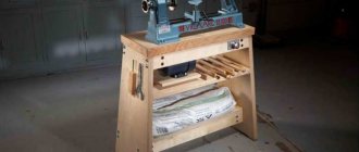
In the household, the functions of a milling machine are usually performed by a manual milling machine. To perform the maximum range of work, the milling cutter is equipped with a whole set of accessories. The main equipment is supplied with the equipment, additional equipment can be purchased or manufactured independently. These are a variety of stops, clamps, templates. But you can go even further and make a copier for milling volumetric parts.
Milling and copying equipment: operating principle
The operating principle of such a device is to clearly transmit the movements of the copy head through the holder profile to the cutting tool.
It is quite difficult to purchase a copy milling machine, so craftsmen make it with their own hands from scrap materials. Everything happens by trial and error. Therefore, experts advise first assembling a duplicate carver, and only then introducing it into mass production. As a rule, this stage is preceded by more than one serious adjustment and alteration.
Homemade wood turning and copying machine with your own hands
Industrial types of copiers are not cheap, so craftsmen choose the option of constructing a homemade machine. It requires little investment of money and effort.
Performance generally depends on the specifications of the copier. The main task of a self-made device is to create parts according to a template without additional energy consumption.
Required Tools
You won’t need many tools; all of them are publicly available and available to every master:
- Manual frezer.
- The cutter is placed on a support, which can be made of plywood 12 mm thick. Metal is used to improve performance. The dimensions of the platform are about 50x20 cm.
- Bolts.
- Thrust bars.
- A pipe with a diameter of 25 mm will allow you to set the direction of movement of the support platform.
The fundamental cutting tool when constructing a lathe with a copier is considered to be a hand cutter. Even though the copier is made of plywood, it is capable of creating many copies.
Design elements
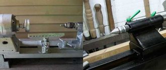
The simplest and most affordable model of the unit is made from a standard drill. Main equipment spare parts:
- Bed.
- Front, rear grandma.
- Electrical engine.
- Leading, driven center.
- Support for equipment.
All processing components are located on the bed. It can be wooden or metal. The headstock is placed on the platform, and the part is fixed to it. There is a device in front that controls the rotation from the engine to the drive shaft to the part.
The rear post moves along the directional axis; it serves to hold the edge of the profile. Between the headstocks there is a stop for equipment. The products must be on the same plane.
Manufacturing stages
If you need to turn a lathe into a copy machine, you will need an additional device - a copier. Stages of machine assembly:
- You should come up with or download a drawing, which will later be used for assembly. Usually this is a diagram of a standard device that adapts to the copier.
- The process begins with the bed, which requires angles and metal sheets. They are connected by welding. Must meet the requirements of reliability and vibration resistance.
- For maximum functionality of the equipment, an electric motor is installed, designed for 200-250 W, picking up about 1500 rpm. For processing large-sized profiles, it is recommended to choose a higher power motor.
- A faceplate is fixed to the shaft. It is equipped with sharp ends that transmit rotational force.
Particular attention is paid to the manufacture of the copier. It is the main difference between a lathe and a copying machine.
How to make a copier for a lathe?
The copier is indispensable in the production of identical parts. Thanks to it, productivity increases. Some aspects of the copier layout include:
- The main unit is a manual milling cutter that is superfluous in the workshop.
- To install it, a plywood surface is required.
- Holes are made and bars are placed for fastening.
- The bars are fastened with self-tapping screws, which securely fix the devices.
- To cut the workpiece, the platform must move easily along the bed.
- When creating a copier, it is necessary to have a level, because any deviation leads to an error.
- The block is placed horizontally. There is a template for it. The beam is fixed with self-tapping screws.
- The design must be created so that, if desired, the copier can be folded out and the device can be used as standard equipment.
The template is made from plywood and screwed to the front of the beam. The upper platform is checked to ensure it matches the axis on the template.
Installation of structural elements
In order for the copying machine to carry out the most efficient work, and the procedure to be of high quality, rush is eliminated. After studying the drawing, you must adhere to the specified parameters.
It is recommended to pay attention to a few tips:
- The axis for tool movement is set parallel to the axis of the workpiece.
- The coincidence of pipe lines and equipment is an important plus.
- It is important that the bottom edge of the router is aligned with the axis of the equipment. This may vary depending on the installation level of the copier.
- It is better to fix the guide pipe with wooden boards through blind holes.
- The bars of the supporting surface should move and slide easily. If they wobble, the structure will have to be rebuilt.
Some masters are concerned about the moment when high requirements regarding sliding are provided. It’s easy to design a machine with excellent options; just select a straight pipe with smooth walls.
Milling and copying equipment: areas of application
Milling copying machines can process not only flat, but also three-dimensional parts. With their help, along with simple milling operations, you can perform engraving, repeat drawings, patterns and inscriptions. The design of the machine is quite simple, and any craftsman can make it.
Copy-milling machines allow you to process not only wooden parts, but also cast iron, steel and plastic workpieces, as well as products made of non-ferrous metals. This is ensured by high-quality tools made of high-speed steel and hard alloys. The copying machine allows you to mill not only straight, but also curved surfaces. In this case, the details are completely identical.
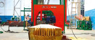
Copy model CL-1201
To produce wood products, a machine model CL-1201 or CL-1500b can be used. The first version has very attractive performance characteristics:
- The spindle used can change the direction of rotation. Due to this, the scope of application of the model is significantly expanded. Changing the direction of rotation of the spindle is carried out with a special handle.
- The machine allows you to select the spindle rotation speed with high precision. Due to this, it is possible to provide the most favorable conditions for turning wood based on the weight, dimensions and type of wood.
- There is a remote control to set basic parameters. The design can be installed on the headstock or tailstock, depending on the preference of the master. The remote control is represented by a combination of several keys.
- Cast iron is used in the manufacture of the column. In addition, the frame is manufactured using high-quality steel. By combining these materials, the degree of vibration of the structure during operation is reduced.
- The basic delivery includes a copier, which can be used for processing. Due to this, costs are reduced and the machine becomes more functional in use.
- The design of the machine has a milling attachment, which can be used to produce longitudinal grooves.
- The tailstock is used for more precise fixation of the workpiece. Its position may also change. The supply includes centers, which are selected depending on the characteristics of the workpiece.
- The support is characterized by high mobility. The cutting depth of the tool can be adjusted using a lever.
In addition, the manufacturer paid quite a lot of attention to the degree of protection of the machine from environmental influences. For example, the engine has a protection system against overheating or overload, all electronic parts are also protected from moisture and dust.
The only but significant drawback is the high cost of the proposal. A homemade design will cost several times less.
Milling and copying equipment: design
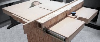
The typical design of a copy-milling machine is completely simple. It consists of a work table and a guide system with clamps for attaching the router and copier.
Making a universal copy-milling machine at home is quite difficult, and there is no great need for it. For home use, equipment with highly specialized specialization is usually created.
Factory or homemade machine?
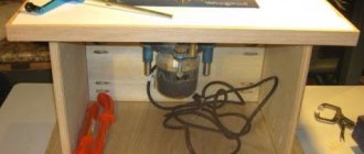
Homemade copying machine
The modern market offers the purchase of milling and copying machines of various levels of complexity and design. But it is not always possible to make such a purchase, and the cost of such woodworking equipment is quite significant. That is why craftsmen often raise the question of a homemade milling and copying machine, the production of which is less expensive than self-assembly. Now, if you have the appropriate drawings, materials and skills, you can make such equipment yourself.
It is clear that this type of homemade equipment cannot compete with factory-produced equipment in terms of its parameters and ease of use. But if performed reliably with a home-made machine, it is possible to make fairly high-quality copies of certain wooden objects.
It should be noted right away that it is almost impossible to install copying equipment on a factory milling machine, since this implies a radical re-equipment of the entire machine.
That is why you can make a copying machine for wood with your own hands only “from scratch”, using systems of rods, an electric motor and a special chuck in which the cutter that processes the workpiece will be held.
Manufacturing of copy milling machine: materials
To create a duplicate carver at home with your own hands, you should draw a basic sketch, which will become a guide to further actions. In addition, you need to stock up on some materials. This:
- Knee cemented polished shaft Ø 16 mm.
- Linear bearings in the amount of 2 pcs.
- Rail guides 900 mm long – 2 pcs. For ease of fastening, their length is taken as a multiple of 150.
- Split linear bearings in the amount of 4 pcs. It is advisable to use bearings with a clamping screw to adjust the tightness of the fit on the guide.
- Profile pipe 30×60 with a wall thickness of up to 3 mm.
- Metal plate 900 mm long and 100 mm wide.
- End posts in the amount of 2 pcs.
- Moving element in the form of a plate – 1 pc.
- Rocker arm for attaching the copier and router – 2 pcs. The length is chosen arbitrarily.
- Movable couplings – 2 pcs.
- Profile pipe 40×40 with a wall thickness of up to 3 mm.
- Crown clutch for turning the part and template.
Copier for lathe
guide pipe
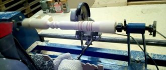
The basis of the copier will be an unnecessary manual router. It is placed on a surface made of 12 mm plywood, the size of the platform is 20 x 50 cm. Holes are made in the platform for fasteners and cutters, and stops are installed - bars for fixing the cutter. The router is placed between the clamps and secured with a pair of large nails.
The remote part of the platform moves along the frame along a guide - a pipe. Its ends are fixed in wooden blocks. The bars are attached to the frame with self-tapping screws. When fixing the pipe, you must use a level and align the axis of the pipe with the center of the machine. Before installation, a pair of bars with holes are put on the pipe and can be easily moved along the guide. A platform on which the router is placed is attached to the bars.
stop-copier
The second important element is installed with your own hands directly on the lathe - a block in a horizontal position on which the templates will be attached. A 7 x 3 cm beam is suitable; it is attached to the vertical stands with self-tapping screws. The stands are screwed to the frame. The top surface of the block must clearly coincide with the axis of the machine.
When the copier is not in use, the block is dismantled, the platform with the milling cutter is moved back and the machine turns into a regular lathe.
The stop is made of thick plywood and is attached to the work surface. In fact, the stop plays the role of a copier in this design. It is fixed vertically and fixed to the end of the working surface on a transition beam made of wood. The copier can be removed, it is installed on the stand with self-tapping screws. The stand must be fixed firmly, without the possibility of removal.
The templates are made of plywood and are screwed to the front surface of the block using self-tapping screws. The upper surface of the beam should be aligned with the axis of the template.
Making a copy-milling machine: tools
After this, you need to prepare a tool that will definitely be useful for assembling the machine structure. This:
- angle grinder;
- cutting and cleaning disc;
- welding machine;
- welding mask;
- petal disc or brush;
- self-tapping screws for fastening rail guides and moving elements;
- electric drill;
- screwdriver;
- measuring instruments: tape measure, caliper;
- center punch and scriber.
Making a copy-milling machine: step-by-step instructions
After everything is ready, the actual assembly of the copy-milling machine begins.
Step #1
It is necessary to cut two pieces 950 mm long from a 30×60 profile pipe to attach the rail guides. A margin of 50 mm is needed for installing limit switches in order to prevent linear bearings from slipping off.
Step #2
The 40×40 profile pipe needs to be cut into blanks for the base. Guided by the existing sketch, you need to cut two pieces of 1350 mm and two pieces of 900 mm.
Step #3
It is necessary to cut small racks from the same pipe. Their linear size depends on the height of the subsequently processed parts.
Step #4
Now you need to remove the rust from the pipes.
To do this, you can use a flap disc or brush. Important ! Before using the brush, pay attention to the maximum number of working revolutions on it and the grinder. The rotation speed on the brush must exceed the speed of the equipment.
Step #5
After this, we weld all the joints and clean the seams with a 6 mm thick cleaning wheel.
Step #6
Then it is necessary to ensure parallelism of the rail guides. To do this, you need to make the connection between the rack and the base of the rail guide detachable. It is necessary to take a washer according to the internal size of the rack, weld a nut to it and screw in the bolt. At this stage, the bolt is needed in order to install the nut and washer in the cavity of the stand pipe flush and in a strictly vertical position, and when welding it, do not damage the thread. This must be done with all four racks.
Step #7
Weld the posts to the base.
Step #8
At the base of the rail guide, at the junction with the racks, you need to drill holes: in the upper shelf for the bolt head, in the lower one for the thread.
Step #9
Install the rail guides on the base (30×60 pipe), pre-drilling holes, and secure with metal screws.
Step #10
Install the bases with rail guides and tighten with bolts.
Step #11
Check the parallelism of the guides. If it is missing, it is necessary to make adjustments by placing foil of different thicknesses on the racks under the guide.
Step #12
On the metal plate you need to mark and drill holes for attaching split linear bearings and end posts.
Step #13
After this, you need to make a movable element by welding 300 mm long rocker arms for the feeler gauge and router to a metal plate, then attach linear bearings to it.
Step #14
After this, the moving element must be placed on a polished shaft, along the edges of which the end posts must be installed.
Step #15
The entire structure must be installed on a metal plate 100 mm wide and the end posts must be secured with self-tapping screws.
Step #16
Then, split linear bearings must be installed on the metal plate on the bottom side.
Step #17
After this, the suspended structure is put on the rail guides with split bearings and the end switches are installed.
Step #18
Movable couplings are installed at the end of the rocker arms and a probe and a milling cutter are attached.
Step #19
In order for the workpiece and the part to rotate synchronously, it is necessary to connect them with couplings. A sprocket and crown are suitable for control. The copy milling machine is ready. The design achieved 5 degrees of freedom. Movement along the X axis is ensured by the movement of the structure along rail guides, movement along the Y axis is ensured by the movement of a moving element along a polished shaft, and movement along the Z axis is ensured by the movement of rocker arms.
Additionally, due to the movable couplings, the probe and the milling cutter can move left and right along the axis of the rocker arm, and it is possible to move the template and the workpiece simultaneously. This makes it possible to process parts of almost any shape.
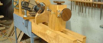
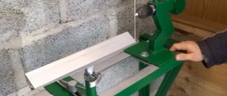
The process of creating a machine with your own hands
Drawings of a homemade mini wood milling machine
Buying a copy-milling machine for wood, especially one equipped with CNC, is beneficial for large manufacturers; in other cases, it is easier to create it yourself.
Before manufacturing a machine, it is necessary to create a drawing and decide how the device will be used. If you plan to work with large products, then the size of the machine should also be large so that the cutter produces less vibration. In addition, you need to select an electric motor of sufficient power. The choice depends on the density of the material you plan to work with.
The number of axes is also determined at the layout stage, since changing the design of a finished machine can be problematic. To work with flat parts, two axes are sufficient: with longitudinal and transverse movement. Workpieces with slight relief also require a perpendicularly moving axis. For more complex products, four or five axes may be needed.
There are many milling machine designs, but they all consist of three elements:
Copy milling machine - device
- working surface;
- bed;
- milling head.
The design of the working surface of the copying machine must provide for height adjustment, and the milling head must be high-speed and equipped with an electric drive.
The layout of a wood copy-milling machine can be vertical or horizontal. The comfort of working with the tool and unloading finished parts depends on this.
Pantograph
Homemade pantograph - drawing
The cheapest option, for the manufacture of which you need several boards and a router. Designed for flat threads.
The shape resembles a parallelogram. Thanks to this design, when moving, nodal points describe equidistant curves. To scale the device, the link is lengthened.
The side of the parallelogram is half as long as the total length with the copying tip. Because of this feature, when copying any part with the tip, the cutter will halve it, which reduces the copier error.
Model with plane-parallel mechanism
Used for contour milling. Unlike the previous model, a curved trajectory is achieved by adding two axes perpendicular to each other. The third axis inserts the cutter into the workpiece.
To balance the system, the design includes a counterweight on the other side of the swing frame. To be able to adjust, it is better to place it on a threaded rod.
Copy milling machine with plane-parallel mechanism
Model for volumetric milling
On such a device, the milling head is placed on a swinging frame, which during processing moves on roller carriages along perpendicular guides. The model and the part are mounted on two rotating units at the bottom of the base. The open frame makes it easy to clean out sawdust.
Copy milling machine for volumetric milling
Duplicarver-2
Serial copy-milling machine for wood, designed for both flat-relief and sculptural carving. The design provides five controlled axes:
- side arms;
- rotating frame;
- milling head;
- work tables;
- lateral movement of the head.
Quite light (weight about 28 kg) for one person.
Duplicarver-2
Duplicarver-3
The design of this model is similar to Duplicarver-2, but has two additional rolling pin guides (another linear axis), and the rotary tables are installed vertically. Thanks to such changes, it became possible to work with long volumetric threads.
Pantograph for a router: principle of operation
The schematic diagram of a pantograph looks quite simple. It is a square divided in half. All joints are hinged, so all sides are movable, and the square easily turns into a rhombus when impacted. The zero point, located in one of the corners of the square, is fixed rigidly. Relatively, its design can be modified, turning into a rhombus. A cutting tool is installed in the middle of the square. A copier is fixed diagonally in the opposite corner of the square. The distance from the zero point to the cutter is a certain value A, and to the copier 2A. This gives a 2:1 scale. The linear size of the long and short sides of the pantograph should also differ from each other by 2 times.
Pantograph for a router: materials
In order to make a pantograph with your own hands, you will need the following materials:
- Square metal profile 12×12
- Bearing 180201.
- Bushings for the outer race of the bearing.
- Pins according to the internal size of the bearing and M12 thread.
- Nut M12.
- Bolts M6×45
- Nuts M6.
- Bushing for securing the copier.
- Profile pipe 40×40
- Hinge of a metal-plastic window.
- Dye.
- Masking tape.
- Metal plate.
- Screw for fixing the copier.
Pantograph for a router: step-by-step instructions for making it yourself
Let's proceed to the actual production of the pantograph.
Stage No. 1. Workpiece cutting
It is necessary to mark and cut the square profile according to the calculated dimensions. For convenience, you can use masking tape and a metal plate. The tape will allow for clear markings, and the plate will help make an even and high-quality cut. The blanks for the platform for the router must be cut at a right angle, and the sections of the profile for the connecting rods must be beveled for maximum fit of the bearing sleeve.
Stage No. 2. Drilling technological holes
All workpieces must be chamfered and holes Ø 6.2 mm drilled for further connection into the structure.
Stage No. 3. Welding the platform for the router
After this, you need to weld the platform for the router.
Stage No. 4. Manufacturing of connecting rods
It is necessary to make something like a jig on the board and firmly fasten all the parts to be welded. To do this, a hole is drilled in the board, and the bearing in the bushing is clamped with a bolt, the square profiles of the connecting rods are secured with clamps. First you need to insert two washers between them and fasten them with bolts. After this, all joints of the structure are scalded and cleaned. Then you need to cut the bearing sleeve between the square profiles on each connecting rod. M6 bolts, washers and bearings must be removed. It is necessary to weld a mount for the router onto the frame, and an extension for scaling onto the short connecting rod at the point opposite the zero point. The connecting rods can be painted to give an aesthetic appearance.
Stage No. 5. Making a unit for attaching a copier
Now you need to machine two bushings with an internal diameter similar to the size of the copier. Drill a hole on the side and cut a thread to install the screw that secures the copier. After this, you need to cut two pieces of 12x12 squares 20-30 mm long and weld them on the side between the bushings. The size between squares should be 12 mm.
Stage No. 6. Manufacturing of the bearing lifting mechanism
It is necessary to manufacture a bearing lifting unit. To do this, the zero point finger must be welded onto a piece of 12×12 profile and secured to a 40×40 profile pipe using a loop from a metal-plastic window. The profile pipe will serve as a place for attaching the pantograph to the table with a clamp.
Stage No. 7. Pantograph assembly
The bearings must be installed in the bushings and secured securely by tightening the square profiles of the connecting rods with M6 bolts. Using your fingers, you need to assemble the connecting rods into a single structure. Secure the pantograph to the table with a clamp and install the router. The device is ready for use.
Classic design
Industrial machines have a rather complex design, especially CNC versions, which can carry out processing automatically. The required product can also be obtained using copying equipment. The classic design is represented by a combination of the following main components:
The bed acts as a base and connecting element. The structure is made using metal, the individual elements are connected by welding. The bed can have different heights. Each craftsman chooses his own height when making a homemade structure.- The headstock and tailstock are also an integral part of the machine. The headstock is used to house the gearbox and drive, as well as the electric motor. The tailstock is used to fix the workpiece, which makes it possible to produce longer products.
- The main rotation is received by the workpiece. It is transmitted from an electric motor through a drive.
- The tool rest also allows for high-quality processing. It is worth securing the cutting area to eliminate the possibility of injury to your hands or contact with a foreign element.
- Leading and driven centers used to secure the workpiece.