Which beam to choose for flooring: dimensions and installation process
In private construction, the interfloor ceiling is usually erected from wooden beams. Firstly, the material is quite accessible, and secondly, it is lightweight, so you can handle the construction of the ceiling on your own and without the use of special equipment. Well, thirdly, wood is an excellent heat insulator.
Choosing timber for floors
What will we talk about:
What does the concept mean?
The load on a concrete hollow-core floor slab is the main operational parameter that determines the load-bearing capacity of the product and reflects how many kg of weight a square meter can withstand. m of surface. Reflects the totality of all types of loads that the slab can withstand while performing its functions.
The permissible load on a hollow-core floor slab is one of the main parameters for choosing this product when designing a building. The strength of the structure and the duration of its operation until the need for major repairs arises depend on the accuracy of the calculation.
What timber is used for the ceiling?
- All you need is well-dried wood - a humidity level of no more than 20%. When drying, the wood changes in volume, sometimes even warping, which will lead to deformation of the ceiling.
- The type of wood, if we are talking about a wooden structure, must match the type of the rest of the wood. The degree of shrinkage and response to temperature changes differs markedly between different materials.
- The bars must be carefully treated on all sides, not forgetting the ends, with antiseptics, since wood is usually susceptible to rotting and is a tasty morsel for insects.
- It is also recommended to treat the material with fire retardants - the compositions increase fire resistance.
When constructing a beam system, a number of other requirements are met that affect the choice of material - its dimensions and manufacturing method. Thus, above rooms with high humidity, the beam system is additionally waterproofed. And if beams separate floors with different temperature conditions - for example, a residential floor and an unheated attic, then the thermal insulation must be strengthened and meet the same requirements as the thermal insulation of walls. In this case, the insulation constitutes a noticeable additional load, and the timber will have to be selected in larger sizes.
Step-by-step instruction
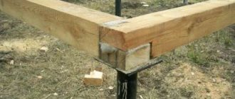
When all the tools are ready, the wood has been processed and cleaned, you can proceed to the main work of cutting out the joints. It looks like this.
- Each working beam is aligned along the edges. To do this, use a square with which to measure each of the 4 sides of the beam, draw a control line and cut it with a chainsaw or circular saw from 2 wide sides. If the disk is not enough along its entire length, the remainder is cut off manually with a hacksaw.
- Next, draw the drawing itself, lines on the beam also on all 4 sides.
- The cuts are made using a chainsaw or hacksaw. If you are not sure that the master will make an accurate cut using a chainsaw, it is better to use a hand saw. In this case, errors will greatly affect the quality of the joints; it will be extremely difficult or impossible to restore or repair them.
- After making the cuts, the unnecessary piece of timber is carefully removed using a chisel and hammer.
- When the excess parts have been removed from both beams, it is necessary to place one beam against the other to check the accuracy of the connection. As a rule, there is always a small gap at the joint; it should not exceed 1 cm. Jute will be laid in this place.
- Next, both parts are glued or connected using bolts, after drilling holes with a drill. The ideal option would be gluing and bolting.
The boards are joined using the overlapping method. Since the lumber is of small cross-section, it cannot be sawed and any, even small parts, cannot be removed. Thus, the boards are connected using 4-6 bolts.
The overlap length varies from 20 to 50 cm depending on the length of the beam itself. When installing finished beams on concrete walls, they must be insulated with roofing felt or similar material so that the board does not come into contact with the surface of another material.
Load Definition
The size of the beam for the floor between floors is determined by the load that the structure must withstand. It’s one thing to have an uninhabited attic, which acts as an air gap between the roof and the home, and quite another thing to have an attic, where the total weight of furniture, people, household appliances and insulation can reach significant values.
The total load is the sum of the mass of all objects and the weight of the structure itself.
For a non-residential attic, the calculation will be approximately as follows:
- if the room is not used as a warehouse, and a lightweight heat insulator was used - mineral or basalt wool, expanded polystyrene, then the dead load is taken as 50 kg / sq. m;
- according to SNiP, the standard load during operation of a non-residential attic space is 70 * 1.3 = 90 kg/sq. m, taking into account the safety factor;
- accordingly, the total load is calculated as 50+90=130 kg/sq.m. m. In practice, the value is immediately increased to 150 to ensure a safety margin.
If old things are folded and stored in the attic, including furniture, if heavy insulation is used, and also when the ceiling is covered with heavy finishing material, the operating load is increased to 150.
- Accordingly: 50+150*1.3=245 kg/sq. m.
It is also recommended to make interfloor ceilings in a house from timber in cases where the second floor is a residential attic. However, when making calculations, it is necessary to take into account the weight of furniture, the floor on the second floor, partitions, if any, and the total weight of permanent residents.
- Typically, the total load is 300–150 kg/h. m.
If the second floor consists of residential, heated, actively used premises, then the total load will be at least 400 kg/sq. m. Determination of the cross-section of timber, both glued and solid, is carried out based on the obtained values.
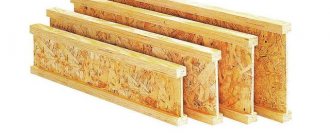
Glued laminated timber
To increase the strength or size of solid beams, they are fastened together manually during installation of the floors. For the same purposes, laminated veneer lumber manufactured at enterprises is used. It consists of several bars connected to each other. The thickness of an individual element is regulated by the number of products glued together. Glued laminated timber is produced at the factory by pressing, its length reaches 12 m.
Finished products retain the characteristics of solid lumber and can be nailed without loss of strength or cut into pieces of the required size. The only drawback of such structures is their high cost. It is necessary to carefully calculate everything before installing the first floor ceiling on wooden beams.
Note! Glued laminated timber is often used in construction for the installation of arched ceilings.
Overlap length
The second fundamental question is determining the dimensions of the material. This parameter is fixed - the material is cut into standard sections, so calculations may lead to wooden trusses being installed instead of beams.
The parameter consists of the span and the depth of embedding of the beam into the wall. In brick partitions, the beam is placed to a depth of 150 mm, in wooden walls - it is cut into the base at 70 mm.
The optimal span is 2.5–4 mm, the maximum is 6 m. If the value is larger, the beams are made of laminated veneer lumber. If the span is very long, additional supporting structures may be needed - columns, partitions. In the photo there is a ceiling assembled from laminated veneer lumber.
Defining parameters
The cross-section of the beam for the floor is calculated in accordance with the established load and the span. The best option is a rectangular section, in which the height and thickness have a ratio of 1.4:1. The width can be 40–200 mm, and the height can be 100–300 mm.
As a rule, the dimensions are selected so that the height exceeds the thickness of the heat insulator.
The distance between the beams ranges from 30 to 120 cm. It depends on the full load, and on the size of the insulation sheet and the sheathing elements. In addition, in a frame building, the distance between the beams should to some extent coincide with the step between the frame posts.
Floor beams made of laminated veneer lumber on the first floor are calculated according to the same scheme: the strength characteristics of the materials are similar.
The results obtained are checked against a reference table to determine the sizes of elements for interfloor slabs. When checking, it is taken into account that the deflection for attic-type structures should be about 1/200, and for residential attics - 1/350.
In the video, the calculation of the parameters of the beam system is illustrated with relevant diagrams and explanations.
Calculation procedure
A preliminary calculation helps determine the pitch of wooden floor beams, their sizes and quantity. Before carrying out such operations you must:
- carry out measurements of the span between the load-bearing walls of a residential building;
- calculate the load that the ceiling will experience after installation;
- carry out calculations of the section and pitch of beams using special tables.
The length of the base beams for the roof consists of the span size and the required margin of 10–15 cm for a reliable ceiling when supported on the wall. Span length is the distance between the internal parts of opposite walls in a residential building or any other building. The most popular option in private construction is considered to be a distance from 2.5 to 4 m. For spans greater than 6 m, wooden trusses are used to install the floor.
Important! The load on a wooden beam includes forces from the structures above, the internal filling of the floor, as well as temporary elements (people, household appliances and furniture).
Accurate calculations can only be performed by a construction organization specializing in this. For independent calculations, use the following values:
- the total standard load per square meter of flooring when using insulation (mineral wool) is 130 kg/m2;
- when using thick boards and heavy thermal insulation material, the standard load increases to 150 kg/m2, the total, taking into account the safety factor of 1.3 - up to 245 kg/m2;
- in the attic room, the ceiling is subject to temporary loads from the installation of furniture or the movement of people - the total load will be 350 kg/m2;
- the total load for interfloor spans is at least 400 kg/m2.
All specified values are considered the base value for further calculations.
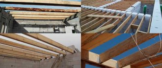
Beams for interfloor slabs: purpose, types, calculation of parameters and installation of beams
Overlapping with timber on an I-beam as an intermediate connection.
Floor beams are used as load-bearing beams that transfer the load from all objects in the room, including the own weight of the floor, to the walls of the structure. These beams serve as support for the floor joists and as the basis for the ceiling finishing.
Thus, we see that we have before us a structural element, the proper use of which requires the correct calculation of such parameters as:
- cross-section of timber for flooring. It is important to select the width and height of the section, as well as their ratio;
- step of arrangement of load-bearing elements over the area to be covered;
- moisture content of lumber. This is also a very important parameter on which the success of the entire event may depend;
- the type of wood used to make beams. Most often it is pine;
- lumber quality. It is important to ensure that there are no cracks, a large number of knots and other defects;
- the presence, extent and composition of wood treatment with protective complexes, including antiseptics, fungicides, fire retardants and insecticides.
the length of the beam in relation to its cross section. There is a maximum length for timber floors, and usually it does not exceed 6 meters, since wooden material cannot reliably cope with large spans;
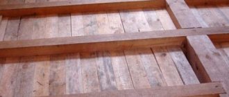
The photo shows the ceiling of the first floor.
For the construction of interfloor structures, massive four-edge material made from northern pine is usually used. The most popular sections are 100x100 mm, 150x100 mm, 150x150 mm, 200x150 mm, 200x200 mm.
It is believed that the greatest load-bearing capacity is possessed by parts whose height exceeds the width by 7:5, and the length exceeds the height by approximately 24 times.
Important! The purpose of timber for interfloor ceilings is to accept, distribute and transmit loads from the weight of people, objects and its own weight to the load-bearing walls of a house or apartment.
Calculations
Calculation of the cross-section will allow you to have no doubt about the strength and rigidity of the structure. In this case, the maximum length that is allowed for any section is determined. To perform the calculation, you need the following data:
- the length of the wooden floor beam (more precisely, the distance between the load-bearing walls);
- the distance between the beams (their pitch);
- load on the structure.
The load consists of two values: permanent and temporary. The permanent includes the mass of the beams themselves (preliminary for now), insulation, ceiling lining, rough and finished floor. The temporary load is the mass of people and furniture. According to regulatory documents for residential premises, it is taken to be 150 kg/m2. For the attic you can take less, but it is recommended to use the same one. This will not only provide a certain margin of safety, but will also make it possible in the future to convert your attic into an attic without reconstructing the load-bearing elements.
The beam frame should be calculated using the following formulas:
In these formulas, q is the load per square meter. m of flooring, which includes the mass of structures and 150 kg of useful value. In this case, these values must be multiplied by the distance between the beams. This is due to the fact that the calculations require a load per linear meter, and initially the value was calculated per square meter. l2 is the distance between the load-bearing walls on which the purlin rests, taken in a square.
Knowing Wrequirement, you can select the section of the floor. W = b*h2/6. Knowing W, you can easily create an equation with one unknown. Here it is enough just to set one geometric characteristic b (section width) or h (its height).
Most often, the wooden beam already has a known width. It is more convenient to make it from a board 50 or 100 mm wide. You can also consider the option with a composite section. It is made from several boards 50 mm thick.
By calculation in this case, the required height of the element is found. But there are cases when you need to fit into a certain ceiling pie so as not to reduce the height of the premises. In this case, the height of the section is added to the equation as a known quantity, and the width is found. But the lower the height, the more uneconomical the floor frame will be.
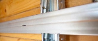
To tighten two or three boards together, it is convenient to use metal pins. In this case, when tightening the nuts, be sure to use wider washers. They prevent the metal from pressing into the softer wood. It is imperative to provide insulation between wood and steel fasteners. For this, you can use a material such as TECHNOELAST brand EPP.
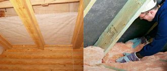
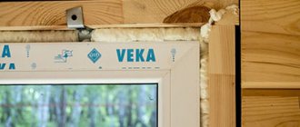
Wooden blocks must be waterproofed before installation
Before using wooden elements, they are treated with an antiseptic composition. This is necessary to prevent mold and rot. It is also recommended to treat with fire retardants, which will increase fire safety. When resting the purlins on a wall made of brick or concrete, their ends are wrapped with technoelast, linocrom, waterproofing or roofing felt.
When constructing private country buildings, many builders use floor beams. The products evenly distribute the forces from the structures above, increasing the rigidity and strength of the entire house. When designing a residential building, it is necessary to calculate the wooden floor beams, select the optimal cross-section and distance between the beams.
Installation of beams
Initially, all necessary calculations are made. When the dimensions, cross-section and pitch of laying the beams are known, installation work can begin. It should be said here that the moisture content of the material is of great importance.
It is advisable that the board is dried to 10 - 12%. Timbers whose humidity exceeds 20% cannot be used in construction, otherwise they will twist strongly along the longitudinal axis.
Most often, special cuts or niches are made in the walls so that the ends of the beams rest on the wall to a depth of 100 - 150 mm. If the walls are brick, concrete or block, then the ends are treated with bitumen mastic or roofing felt to prevent rotting from absorbed moisture.
The width of niches in stone walls is selected so that the board is concreted with a 50-100 mm layer of cement-sand mixture. Fastening is also practiced using steel baskets, plates, brackets and other similar parts.
In this case, the brackets themselves are attached to the walls with anchor bolts or dowels, and the beams are inserted into the landing cup and secured with self-tapping screws.
In frame houses, when calculating the pitch of laying wooden beams, they try to take into account the location of the wall racks of the partitions; this principle makes it possible to create a more reliable and durable frame.
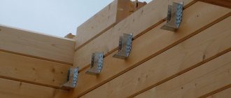
Fastening floor beams in a log house with steel brackets.
Important! Wooden floors conduct sound vibrations well, so it is advisable, regardless of temperature conditions, to lay mineral wool between the beams and use sound-absorbing pads.
Self-production of glued elements
There are several options for making laminated veneer lumber yourself:
- combination of three elements into one structure;
- gluing two parts in the shape of a Z symbol;
- connection of lamellas using special elements, metal inserts.
The first method is considered the most practical; it is much simpler than the other two. At the initial stage of work, boards for timber are selected and laid on the central element so that the annual rings of the wood face in opposite directions. Marks are made on the surface of the boards with a black marker or a simple pencil, which will indicate the sequence of their laying.
The central element is cleaned on both sides with sandpaper, which will create a rough surface and improve glue adhesion. Side boards are processed only at the point of contact with the main beam. At the next stage of work, the surfaces are degreased with a solvent, an antiseptic and fire retardants are applied. These liquids and protective compositions are applied alternately: first the solvent, then other impregnations after the base composition has dried. Not only the sides of the lumber are processed, but also the ends.
Now you need to apply a thin layer of glue (1-2 mm) to the cleaned and pre-treated surfaces. The top and bottom boards are laid on the central beam so that they are in the same plane. To fasten the elements, clamps are used, which are installed on the beam every 40–50 cm. The curing time of the glue is indicated by the manufacturer (usually does not exceed 2 days).
How to use timber floor beams
When building any private house, you always have to make various types of floors. These can be interfloor or attic structures, but in any case, their installation must be approached responsibly and the most suitable materials must be chosen for this.
We can say that these structures are as integral an element of any home as the walls, foundation or roof.
In the photo there are beam ceilings.
Metal beams: traditional reliability
When a developer has the opportunity and request for more ambitious and large-scale construction, he uses metal floor beams of various sections: a corner with different flange sizes, a channel, a T-beam, an I-beam. If we exclude the possibility of metal corrosion, then in terms of strength there is no substitute for such beams. But the use of metal in individual housing construction is limited by a number of other indicators:
- it is difficult to work with metal at heights;
- special mechanisms for installation are required;
- welding, cutting metal and protecting it from corrosion are additional costs;
- high cost of material;
- metal beams must be insulated from the attic side.
Metal beams also have positive aspects:
- they don't burn;
- more durable;
- metal spans can be made longer and the distance between the floor beams can be greater;
- The types of metal beams are very diverse and allow you to create structures of almost any complexity.
In any case, it is better to entrust the calculation of a metal beam to professionals.
This might be interesting!
In the article at the following link, read about a flat roof in a private house.
Calculation of the cross-section of wooden beams
The photo shows a drawing of the assembled interfloor floor.
When constructing most private houses, developers make the ceiling of the second floor from timber. This is a relatively inexpensive, but at the same time quite reliable material, which has been used for similar purposes for several centuries. The only necessary condition is the correct calculation of the cross-section of such crossbars installed in the span as joists.
To more accurately determine the cross-section of the timber for the ceiling, special formulas are used, which, among other things, take into account the resistance of the wood used and its moisture content. These parameters are defined in SNiP II-25-80, which any developer or private craftsman must be familiar with.
There you can also find the necessary formulas and tables with the help of which the parameters of beams for specific interfloor structures are determined.
When calculating wooden floors, it is also necessary to take into account the width of the span, the distance between the beams, and the shape of their section. When calculating each cross member to be laid, it must be remembered that the amount of its deflection under load should not exceed 1/250 of the span length.
Since it is quite difficult for a technically untrained person to correctly calculate the lag parameters using formulas and tables, you can use special calculators to independently select beams. It is enough to enter several basic values into such a program, and as a result, you can select the correct sizes of load-bearing joists.
Calculation of beam cross-section
The photo shows a table for selecting a beam section.
As an example, using one of these calculators, we will try to calculate which beam to use to cover 5 meters.
To enter data we need to know:
- the material from which the crossbar is made (only coniferous trees are recommended);
- span length;
- beam width;
- beam height;
- type of material (log or timber).
In order to make correct calculations, we substitute the span width equal to 5 m to the entered values, and set the beam type to timber. We will select the height and width experimentally in the parameters “dimensions of timber for floor beams”. You should definitely take into account values such as load per kgm and the pitch between the cross members.
For interfloor structures, the load value should not be less than 300 kgm, since it is necessary to take into account not only the weight of furniture and people, but also the weight of the materials themselves from which the floor is made. This includes floor beams, rough and finished floors and, of course, insulation and sound insulation.
Advice. For non-residential attic structures, a load value of 200 kg/m will be quite sufficient.
Possible options
Photos of beams of different sections.
At almost all bases that sell lumber, floor timber is sold mainly in several sizes. As a rule, these are beams from 100x100 mm, to 100x250 mm, and from 150x150 mm to 150x250 mm. In order not to waste unnecessary time and money searching for logs with non-standard sizes, the price of which can be significantly higher than standard ones, we substitute into the program those parameters that are commercially available.
To do this, you must first find out from the lumber database what sizes they sell. Thus, we find that for interfloor structures the minimum size of timber should be approximately 100x250 mm, and for attic structures 100x200 mm will be sufficient, with a step between them equal to 60 cm.
If you do not trust software calculators and want to independently calculate the size of the timber for the floor, then you will have to use the formulas and tables given in the relevant technical documentation. Or you can use the general rule, which states that the height of each joist should be equal to 1/24 of the length of the opening, and its width should be equal to 5/7 of the height of the crossbar.
What types of beams are there?
There are several criteria by which wooden floor beams are classified: by size, material, type of section. The length of the floor beams depends on the distance between the walls. To this value you need to add a margin for support on both sides . Optimally, you need to provide 200-250 mm.
Based on material, elements are divided into the following types:
- from solid timber or boards;
- from laminated veneer lumber.
Bent beams are made from laminated veneer lumber
The latter are significantly more expensive. But such material is suitable for covering large spans. A regular beam can work at distances of 4-6 m, while a laminated beam copes well with distances of 6-9 m. Glued laminated timber practically does not shrink, is fireproof and resistant to moisture. It is possible to produce not only linear elements, but also bent ones. A significant disadvantage of such a material will be the presence of non-natural components (glue).
The cross-section of beams can be of the following types:
The latter has widened elements at the top and bottom. In the middle of the section it is reduced to the maximum possible size. This option allows you to rationally use wood and reduce its consumption. But making such an element is not easy. For this reason, I-beams are not often used in construction.
The most commonly used timber is rectangular in shape.
The best option would be a rectangle. In this case, the long side is located vertically, and the short side is horizontal . This is due to the fact that increasing height has a better effect on strength than increasing width. Installing a beam from a board flat is practically useless.
The most unfavorable of the presented ones can be considered a square section. It is least adjusted to the diagram of forces in the element.
You can also use logs for roofing. But this option did not gain popularity. The section from the board is much more profitable and easier to install, therefore it is used much more often.
Installation of interfloor and ceiling slabs on wooden logs
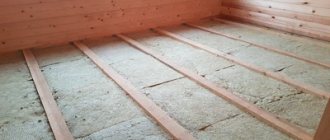
The photo shows interfloor ceilings.
Interfloor ceilings in a house made of timber begin to be installed by laying the logs. To do this, prepared timber is placed on the walls, which is pre-wrapped with roofing felt. This will protect the wood from moisture penetration and, as a result, from rotting.
The outer beams should be laid no closer than 5 cm from the wall, and the distance between adjacent crossbars should not exceed the previously calculated values, which in our case are equal to 60 cm.
An important condition is that the logs must be laid over the entire thickness of the walls, having maximum support and stability. The gaps between the joists on the wall are filled with bricks or building blocks, after which a subfloor made of 150x25 mm edged boards is laid on top.
Ceilings made of timber are almost completely identical to interfloor ones, with the only difference being that the thickness of the beams may be smaller, and the step between them may be several centimeters larger.
Prefabricated timber
The photo shows prefabricated timber.
Quite often there is a situation when there is no lumber on sale, in particular, timber of the required size. In this case, there are several ways in which it is quite possible to solve this problem. The first method is to use prefabricated beams in the construction. You can easily do it yourself using a screwdriver or drill. (see also the article Joining timber along the length - connection options)
Let's say you need logs measuring 150x250 mm, but there are no such sizes on sale, but boards with dimensions 50x250 mm are always in abundance at any lumber base. In order to get a beam of the desired size, it is enough to buy 3 such boards and fasten them together.
It is better to use wood screws rather than nails as fasteners, since over time the wood dries out and the nails do not hold the boards together so firmly.
As the instructions for making prefabricated joists yourself advise, if you use them for basement or basement floors, then before tightening them with self-tapping screws, you should treat each board with an antiseptic.
This will prevent the appearance of wood pests and will significantly increase the service life of the entire floor. If you use prefabricated timber for interfloor slabs, then no pre-processing of the boards is required.
The admissibility of using this type of lag is obvious and is not questioned. This material is as environmentally friendly as regular timber, since no adhesives are used during assembly.
Attention! The load-bearing capacity of prefabricated timber is even higher than that of solid lumber, and the cost is slightly lower. From all of the above, it becomes clear that in some cases the use of prefabricated elements is even preferable to solid ones.
Glued laminated timber
Photo – laminated timber.
This type of lumber is an acceptable alternative if the required solid logs cannot be found, or their price is high enough for you, and it is not possible to make a prefabricated structure yourself.
Glulam beams are made from several boards of different lengths, fastened together using a two-component structural adhesive, which is used in the manufacture of wooden load-bearing building structures. (see also the article What are the advantages of laminated cedar beams)
Floor beams in a wooden house made of laminated veneer lumber are characterized by good strength and resistance to loads, but they also have some disadvantages.
- Due to the fact that adhesives are used in their production, such material can no longer be called environmentally friendly.
- In their production, a fairly large percentage of low-quality lumber is used. Significant shrinkage is possible after several years of use, which means that a laminated timber floor may “sag” over time.
- And the main disadvantage of glued beams is their limited service life, which is determined by the manufacturer at 20 years.
To calculate the volume of lumber, you can use the calculator:
Using boards and solid timber
In the case of using solid wooden beams or boards for flooring, the span length is chosen within 4–6 m, which is half the maximum distance when using building structures made of laminated veneer lumber. Parts made from bonded boards are often manufactured directly on the construction site.
The strength of the structure is superior to solid beams. The main advantage of the products is the possibility of constructing a composite part from several boards. Builders can independently regulate the thickness of the beam by fastening the required number of elements. The boards are connected to each other using threaded elements. Rubber or plastic washers are installed under the bolts and nuts. The elements prevent the effects of corrosion on metal embedded parts and protect the wood from cutting into the nut when tightening.
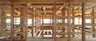
Features of floors
The photo shows the installation of floors.
Based on the experience of professional and independent developers, we can say with confidence that it is the wooden structures of interfloor slabs that are the most popular and often manufactured in the construction of private houses. (see also the article Cottages made of timber, advantages and disadvantages of the material)
This is due to several factors, of which the main ones can be identified:
- ease of installation (2 people are enough to manufacture them, and there is no need for specialized equipment, such as in the manufacture of reinforced concrete structures);
- low cost compared to all other types of structures;
- sufficient strength, reliability and durability;
- ease of repair and dismantling.
For more information about timber floors, watch the video in this article.
Advantages and disadvantages
The wooden blocks that are used for flooring have their strengths and weaknesses.
The main advantages of beams made from boards are:
- minimal weight of structural elements, which reduces the load on the load-bearing walls and foundation of the building;
- beautiful appearance;
- the possibility of installing a plank floor without additional preparation;
- high speed of installation work without the help of lifting mechanisms;
- It is possible to repair the ceiling during the operation of a residential building.
The disadvantages of wooden structural elements include:
- the need to impregnate wood with antiseptics and fire retardants; such solutions prevent rotting and combustion of the material;
- lower strength indicators compared to metal or reinforced concrete products;
- deformation and shrinkage of the structure as a result of sudden temperature changes or under the influence of high humidity.
Note! The installation of a wooden floor is possible on enclosing structures made of aerated concrete, brick or on walls made of any other material.
Wooden floor beams: dimensions and calculations
| Building a house - Do-it-yourself ceilings of a private house |
| In order to build a reliable wooden floor, it is necessary to select the correct dimensions of the beams, and for this it is necessary to calculate them. Wooden floor beams have the following main dimensions: length and cross-section. Their length is determined by the width of the span that needs to be covered, and the cross-section depends on the load that will act on them, on the length of the span and the installation pitch, that is, the distance between them. In this article we will look at how to independently make such a calculation and select the correct beam sizes. The content of the article: |
Pros and cons of wooden floors
To install the ceiling yourself, you need to prepare. The floor in the house must rest on a strong and rigid structure. Before starting work, you will have to study the requirements for the elements, the features of their calculation and the types of sections.
The following advantages of wooden flooring can be highlighted:
- attractive appearance, the ability to make a wooden floor without additional measures;
- light weight, reduced load on walls and foundations, savings on construction;
- possibility of carrying out repairs during operation;
- speed of installation, execution of work without additional machines and mechanisms.
Wooden beams do not weigh down the structure and are quickly installed
But it is also worth highlighting the disadvantages:
- flammability of wood, the need for special impregnation with fire retardants;
- lower strength compared to reinforced concrete or metal elements;
- shrinkage and deformation due to changes in temperature and humidity;
- susceptibility to rot, mildew and mold at high humidity, it is necessary to treat with antiseptics at the construction stage and periodically during the service life.
Calculation of wooden floor beams
In order to determine how many wooden beams and what sizes will be required for the floor installation, you must:
- measure the span that they will cover;
- decide on ways to secure them on the walls (to what depth they will go into the walls);
- make a calculation of the load that will act on them during operation;
- using tables or a calculator program, select the appropriate pitch and section.
Now let's look at how this can be done.
Length of wooden floor beams
The required length of floor beams is determined by the size of the span that they will cover and the margin required to embed them in the walls. The length of the span is easy to measure using a tape measure, and the depth of embedding in the walls largely depends on their material.
In houses with brick or block walls, beams are usually embedded in “sockets” to a depth of at least 100 mm (board) or 150 mm (timber). In wooden houses, as a rule, they are laid in special notches to a depth of no less than 70 mm. When using special metal fastenings (clamps, angles, brackets), the length of the beams will be equal to the span - the distance between the opposite walls on which they are fastened. Sometimes, when installing roof rafters directly on wooden beams, they are extended outward, beyond the walls by 30-50 cm, thus forming a roof overhang.
The optimal span that wooden beams can span is 2.5-4 m. The maximum length of a beam made from edged boards or timber, that is, the span that it can span, is 6 m. For longer spans (6-12 m), it is necessary to use modern wooden beams made of laminated veneer lumber or I-beams, and you can also rest them on intermediate supports (walls, columns). In addition, to cover spans longer than 6 m, wooden trusses can be used instead of beams.
Determination of the load acting on the floor
The load acting on the floor along wooden beams consists of the load from the own weight of the floor elements (beams, inter-beam filling, lining) and permanent or temporary operational load (furniture, various household devices, materials, weight of people). It usually depends on the type of floor and its operating conditions. The exact calculation of such loads is quite cumbersome and is carried out by specialists when designing the floor, but if you want to do it yourself, you can use its simplified version given below.
For an attic wooden floor that is not used for storing things or materials, with light insulation (mineral wool or others) and lining, the constant load (from its own weight - Rown) is usually taken within 50 kg/m2.
The operational load (Rexpl.) for such an overlap (according to SNiP 2.01.07-85) will be:
70x1.3 = 90 kg/m2 , where 70 is the standard load value for this type of attic, kg/m2, 1.3 is the safety factor.
The total design load that will act on this attic floor will be:
Rtot.=Rown.+Rexpl. = 50+90=130 kgm 2 . Rounding up we take 150 kg/m2.
If the design of the attic space will use heavier insulation, material for inter-beam filling or lining, and also if it is intended to be used for storing things or materials, that is, it will be used intensively, then the standard load value should be increased to 150 kg/ m2. In this case, the total load on the floor will be:
50+150x1.3 = 245 kg/m2 , rounded to 250 kg/m2.
When using attic space to construct an attic, it is necessary to take into account the weight of floors, partitions, and furniture. In this case, the total design load must be increased to 300-350 kg/m2.
Due to the fact that an interfloor wooden floor, as a rule, includes floors in its design, and the temporary operational load includes the weight of a large number of household items and the maximum presence of people, it must be designed for a total load of 350 - 400 kg/m 2.
Section and pitch of wooden floor beams
Knowing the required length of wooden floor beams (L) and determining the total design load, you can determine their required cross-section (or diameter) and laying step, which are interconnected.
It is believed that the best is a rectangular section of a wooden floor beam, with a ratio of height (h) and width (s) of 1.4:1. The width of the beams, in this case, can be in the range of 40-200 mm, and the height 100-300 mm. The height of the beams is often chosen so that it corresponds to the required thickness of the insulation. When using logs as beams, their diameter can be in the range of 11-30 cm. Depending on the type and cross-section of the material used, the pitch of the wooden beams
the ceiling can be from 30 cm to 1.2 m, but most often it is chosen within 0.6-1.0 m. Sometimes it is chosen so that it matches the size of the insulation boards laid in the interbeam space, or ceiling sheets. In addition, in frame buildings, it is desirable that the pitch of the beams corresponds to the pitch of the frame posts - in this case, the greatest rigidity and reliability of the structure will be ensured.
You can calculate or check the already selected dimensions of wooden floor beams using reference tables (some are given below) or using the online calculator “calculation of wooden floor beams”, which is easy to find on the Internet by typing in the corresponding query in a search engine. It is necessary to take into account that their relative deflection for attic floors should not be more than 1/250, and for interfloor floors - 1/350.
Table 1
Recommended cross-section of timber beams (sxh), depending on the pitch of their laying and the span to be covered, with a total design load of 350-400 kg/m2 (interfloor floors), mm:
Step , m Span , m
Flooring with boards 200 by 50 and other common sizes
These are the types of beams on a span of 4 meters that are allowed by the standards.
Most often, in the construction of wooden floors, boards and timber of the so-called running sizes are used: 50x150, 50x200, 100x150, etc. Such beams meet the standards ( after calculation ) if it is planned to cover an opening of no more than four meters.
For floors 6 or more meters long, the dimensions 50x150, 50x200, 100x150 are no longer suitable.
Wooden beam over 6 meters : subtleties
A beam for a span of 6 meters or more should not be made of timber and boards of standard sizes.
You should remember the rule: the strength and rigidity of the floor depend to a greater extent on the height of the beam and to a lesser extent on its width.
A distributed and concentrated load acts on the floor beam. Therefore, wooden beams for large spans are not designed “end-to-end”, but with a margin of strength and permissible deflection. This ensures normal and safe operation of the ceiling.
50x200 - overlap for an opening of 4 and 5 meters.
To calculate the load that the ceiling will withstand, you must have the appropriate knowledge. In order not to delve into the strength of strength formulas (and when building a garage this is definitely redundant), an ordinary developer just needs to use online calculators for calculating wooden single-span beams.
Leo060147FORUMHOUSE user
A self-builder is most often not a professional designer. All he wants to know is what beams need to be mounted in the ceiling so that it meets the basic requirements for strength and reliability. This is what online calculators allow you to calculate.
These calculators are easy to use. To make calculations of the required values, it is enough to enter the dimensions of the logs and the length of the span that they must cover.
Also, to simplify the task, you can use ready-made tables presented by the guru of our forum with the nickname Roracotta.
RoracottaFORUMHOUSE user
I spent several evenings to make tables that would be understandable even to a novice builder:
Table 1. It presents data that meets the minimum load requirements for the floors of the second floor - 147 kg/sq.m.
Note: since the tables are based on American standards, and the sizes of lumber overseas are somewhat different from the sections accepted in our country, you need to use the column highlighted in yellow in the calculations.
Table 2. Here is data on the average load for the floors of the first and second floors - 293 kg/sq.m.
Table 3. Here is the data for the calculated increased load of 365 kg/sq.m.
see also
Comments 41
Well, there’s Vladirom’s calculator, enter the span and pitch of the beams vladirom.narod.ru/stoves/beamcalc.html
I have a studio hall-kitchen size 5.80 * 9.60 laid I-beam 200 equal-flange 2 pieces of 6 meters between them, 3.15 meters each, 150 * 150 timber and 50-KA board. During the construction of the 2nd floor, 14 sibit pallets were installed, the deflection in the middle was 4 mm.
This is specifically so as not to write the same thing. I posted a cheat sheet a year ago: vk.com/expertm_nsk?w=page-118571856_52625662
When bent, a beam tends to twist into a spiral. To minimize subsidence when walking, you can make diagonal supports from 50x50 timber across the beams themselves or install crossbars from sections of these beams. The ceiling will be stiffer and sag less. The beams themselves are at least 100x200 mm, pitch 600. PS. I couldn't find a drawing with cross braces.
150x200 should be enough. It is better, as written below, to assemble with boards. The main thing is not to spare nails. The width between the beams is standard 600mm.
Now they are blocking me with timber 100x150 every 80
100*200 through a swing of 90-100 cm laying is sufficient with a margin if the length is no more than 6 meters
room length 5.3 width 6.4
so, it seems that it is accepted that the length is greater than the width)) for you it’s the other way around. Beams, if your width is normal, are 100*200. I have these at a length of 5.6 m and everyone says that with a margin, only So that the distance between them is no more than a meter, I laid them 90 cm apart.
Assemble a “butterfly” beam - three 50x200 boards per edge, with wooden spacers between them, tighten them with pins along the spacers, the beam spacing is 600mm. Other things being equal, the “butterfly” is stronger than a whole beam of the same section, because spatial rigidity appears in it
what is a butterfly beam
Assemble a “butterfly” beam - three 50x200 boards per edge, with wooden spacers between them, tighten them with pins along the spacers, the beam spacing is 600mm. Other things being equal, the “butterfly” is stronger than a whole beam of the same section, because spatial rigidity appears in it
Assemble a “butterfly” beam - three 50x200 boards per edge, with wooden spacers between them, tighten them with pins along the spacers, the beam spacing is 600mm. Other things being equal, the “butterfly” is stronger than a whole beam of the same section, because spatial rigidity appears in it
so the ceiling height will be 660cm
So I thought I’d throw two beams one hundred and fifty on top of each other and sew them together. since the height of my gas block is three hundred mm
I made 50 by 150 boards and the floor rests on them and I’m making a second floor. They jump a little when you jump on them. but my step is 1100-1200, initially I didn’t think that there would be a second floor.
By the way, the strength of strength material will help you - the deflection of a beam under a uniformly distributed load is considered... The moment of inertia of a rectangular section is also... It is more difficult to find reliable information about the modulus of longitudinal elasticity of wood, but you are unlikely to be mistaken by an order of magnitude...
By the way, I remembered another valuable tip - wooden beams should be made with the so-called bending, so that under the influence of a constant load the beam will bend and take a rectilinear shape...
Builders are unlikely to bother with stretching the beam... (it’s more convenient to bend it and fix it in this state...),
Do you think the author of the article understood you?
Concrete slabs are better))) In general, the neighbor laid thicker timber, otherwise it would sag.
Or you can fasten 2 200*50 boards together and use them as timber, it’s stronger))
10x20 will be good, the distance between the beams often depends on the flooring, often it is OSB, so they select it so that the beam fits at the junction of the slabs. But it’s not worth more than 60, the flooring will sag even when walking, and will creak. There are options for floors with double beams, thicker for the floor of the 2nd floor and thinner between them for the ceiling of the first.
It’s better to put a gun carriage
With a span of 5 m, I laid 400x100 (2 x 200x100, fastened together) with a step of 700 mm (between lags of 600 mm - the size of the foam block). During the construction process, pallets with 500 kg foam blocks, 4 pieces each, were placed on a pair of such logs. There was a deflection in the center
2 x 200 in height? How did you fasten it?
Yes, 2x200 in height. Studs all the way through. 5 pieces each. But you should do it like this, just screw the boards at an angle of 90 degrees to each other.
I built two houses. The first one was for myself at the age of 23. The green one didn’t know much. I put 1009120)*200. The result is, in principle, normal, but when children play and jump, it’s not very comfortable. The second time I ordered 100 (120) at 250. In the end, they brought 150 to 250 for the same price. Very heavy, but the difference is noticeable in the noise and shaking of the chandelier))). The larger the rib, the less deflection, vibration, etc.
Article rating:
Save to:
Which timber to use to cover 5 meters Link to main publication
An example of a simplified calculation of a floor covering.
Option 1. Floor covering made of floorboards.
(return to main content)
If the distance between the axes of the beams is 1 m and the width of the beams is 10 cm, the clear distance between the beams will be 0.9 m. This distance will be the design span. But with the calculated load, everything is somewhat more complicated, in principle, 1 person weighing 100 kg, stepping on a board in the middle of the span, will create at least a dynamic load, and possibly an impact if he jumps on the floor or falls from somewhere. In principle, such a concentrated dynamic load of 100 kg applied in the middle of the span is approximately equivalent to a static uniformly distributed load of 400 kg/m, taking into account the dynamic coefficient. But this load will be applied to a maximum of 2-3 boards, and if the boards are not tongue-and-groove and do not transfer part of the load to the adjacent ones, then to one. In this regard, the conditional width of the floor covering will depend on the type of floorboards and their width. For example, with a tongue-and-groove floorboard width of 12 cm, the conditional width of the floor covering can be taken as b = 36 cm
The maximum bending moment will be:
Mmax = ql2/8 = 400x0.92/8 = 40.5 kgm or 4050 kgm
In this case, the design scheme for the boards, as for a single-span beam on hinged supports, is adopted very conditionally. It is more correct to consider wall-to-wall floorboards as a multi-span continuous beam. However, in this case, it will be necessary to take into account the number of spans and the method of attaching the boards to the joists and the possible change in the length of the spans under different combinations of loads. If in some areas boards are laid between two joists, then such boards should really be considered as single-span beams and for such boards the bending moment will be maximum. It is this option, as the most unfavorable, that we will further consider. However, for two-span beams the value of the bending moment will be the same.
The required moment of resistance of the boards according to formula (147.2) and with a design resistance of 130 kg/cm2:
Wreq = 4050/130 = 31.15 cm3
With our adopted width of 36 cm, the minimum permissible board height, according to formula (147.4), will be 2.27 cm; with smaller spans, the required board height will be even less. This means that the floor can be laid with standard floorboards 30-35 mm high with grooves and tenons, allowing you to slightly redistribute the load on adjacent boards, but it is still advisable to check them for deflection with such a span.
But instead of expensive floorboards, you can use cheaper sheet materials, for example, plywood, chipboard, OSB.
Option 2. Plywood flooring.
(return to main content)
The design resistance of plywood can be determined from the following table:
Table 6. Design resistance values for plywood, according to SNiP II-25-80 (SP 64.13330.2011)
As you can see, depending on the direction of installation, the calculated resistance can change by more than 2 times. Why this is so is discussed separately, but here we note that when laying plywood you need to pay attention to the direction of the fibers of the outer layers.
Let's continue the calculation. For example, for birch plywood brand FSF
Rf = 160 kgf/cm2
then the required moment of resistance of plywood is
Wreq = 4050/160 = 25.31 cm3
For plywood, the conditional width of the coating will, of course, be greater than for boards due to better redistribution of the load, but I still would not accept a conditional width of more than 50 cm (the details of the possible redistribution of stresses in the plates are not considered here). With this width, the minimum permissible thickness of plywood according to formula 147.4 will be 1.74 cm, i.e. plywood with a thickness of 18 mm or more can be laid on beams with a distance between the axes of the beams of 1 m.
The maximum deflection for a plywood sheet considered as a single-span beam on hinged supports will be:
f = 5 4 904/(384 90000 24.3) = 1.56 cm
where I = 50·1.83/12 = 24.3 cm4, E = 90000 kgf/cm2 - for birch plywood.
If 2 m long sheets are used for the flooring, then they can be considered as a two-span continuous beam. In this case, the deflection will decrease by about 2 times, but will still remain quite large. To reduce it, it is advisable to use plywood with a thickness of at least 20 mm.
If the distance between the axes of the beams is 0.75 m, and even more so 0.5 m, the value of the bending moment will decrease, and the dimensions of the required section will correspondingly decrease. It is not difficult to make calculations for such distances between the axes of beams using the above algorithm.
General note : in general, when calculating wooden structures, a bunch of different correction factors are used, but I decided not to complicate the above calculation with coefficients; it is enough that we took the maximum possible load and, in addition, there is a good margin when selecting a section. And yet, if plywood is always laid on 4 or more joists, then in this case the maximum deflection will be even less. More details in the section “Statically indeterminate structures”
Cases of slab deflections
There are products on sale with different deflections (in both directions) .
In accordance with SNiP 2.01.07-85 - allowed if it is no more than 1/15 in length. For example, according to PB 90-12 (a particularly problematic product) it can be up to 60 mm.
The occurrence of significant reverse deflection is possible if the slab is short - when sawing, it bends under the influence of significant compressive force. Usually builders can see deflections with the naked eye if the slabs are stacked.
Types of permissible load on structures
The design of any ceiling includes three parts:
- The upper one - with flooring, screeds and insulation (when there is another living space on the floor above).
- The lower one - with ceiling decoration and hanging elements (when housing is also located on the floor below).
- Structural – a load-bearing base on which all the elements of a given part of the structure are mounted (which is the floor slab).
The floor and ceiling with decoration and furniture and interior items located on them, including suspended ceilings, decorative partitions, additional plumbing, children's swings, sports equipment, etc., which are possible in the apartment, provide a constant static load on the floor slab.
Temporary (dynamic) load is understood as that which occurs when people and pets move along the floor structure. At the same time, the calculations even take into account, for example, that all members of the family who will live in a given room may turn out to be obese people, and they will choose as a pet not some light hamster, but large lynx or deer, moving rapidly, almost constantly on the move.
The location of point and distributed loads is taken into account separately. An example of a point one is a suspended punching bag weighing 220 kg, a distributed one is a suspended ceiling system, in the frame of which hangers for the panel are located at a certain distance from each other, attached to the floor slab.
There are nuances in the calculations of point and distributed loads - it is necessary to take into account the functional purpose of the room. Thus, when installing a bathtub with a volume of 520 liters, which, when filled with water, will create a distributed load (due to the area it occupies), the point load from its legs is also calculated separately.
Thus, loads can be permanent - when the entire service life is affected by overlying structures, engineering equipment, communications, etc., and temporary - in three positions:
- Moving living objects indoors, adding new household items and rearranging them.
- Seasonal and weather factors - precipitation (accumulation of rainwater and snow on the roof, eaves and balconies), strong wind.
- Anticipated emergency situations, for example, a collision of a heavy vehicle with a part of a structure or a tower crane falling onto the wall if another construction site is being built nearby, and other similar cases.
In accordance with the coefficients specified in the construction documentation, a standard 6 m hollow core slab (for example, PK 60-15-8), without taking into account its own weight, can withstand the following loads:
- Spot: 1040 kg/m2.
- Distributed: 960 kg/m2.
- Constant: 880 kg/m2.
- Temporary: 1040 kg/m2.
- Limits:
- Minimum: 400 kg/m2.
- Maximum: 1040 kg/m2.