A circular saw, or simply a circular saw, is the most necessary equipment, primarily for independent wooden construction. If you buy rough sawn timber at a sawmill, condition it and cut it into long lengths yourself using a circular saw, the estimated cost of construction literally drops significantly. A circular saw is also necessary for various types of finishing work, for those who like to tinker, and it will be useful just around the house. A factory-made stationary circular saw is very, very expensive, but it is quite suitable for household needs or, say, building a shed, it can be built from scrap trash; only a few turned parts will have to be ordered externally. This article describes how to make a stationary circular saw with your own hands, how to adapt it for jointing and sawing across or at an angle, and also describes homemade accessories for using a manual circular saw as a stationary one.
Which one should I do?
The first question is what depth of cut is needed? The teeth of the saw blade must enter the material at a certain small angle, otherwise the cut will be jagged and the work will become dangerous. The tooth entry angle determines the permissible protrusion of the saw blade above the work table. For discs with teeth of different profiles, the protrusion sizes are somewhat different, but, in general, there is no need to “push out” the disc by more than 1/3 of its diameter - it can “bite”, which will create a dangerous situation.
So, depending, first of all, on the required depth of the circular saw, different types of designs are made with your own hands; The required length of cut also matters a lot. For cutting wood thickness of approx. up to 120 mm you need a disc with a diameter of 350 mm. The cutting thickness can be doubled by making each cut twice on opposite sides, but then the loose length will need to be trimmed. In this case, you need a stationary woodworking machine with a saw blade and a jointing drum, pos. 1 in Fig. The length of the cut on it is determined by the length of the workpiece and the size of the workshop. An asynchronous motor of 1.2-2 kW is sufficient for the drive; an electric motor of such power can be found with a single-phase 220 V. If you want to build very cheaply by preparing unbarked round timber, then you need a much more complex sawmill, not a circular sawmill.
Types of homemade circular saws
For clean sawing on site during finishing work (for example, on site) for a length of up to 1.5-2.5 m, incl. at an arbitrary angle, a hand-held circular saw with a guide rail, branded (item 2a) or homemade (item 2b) is required. You can also build a circular table with a side stop for it (items 3a and 3b). The length of the cut becomes unlimited (within the premises), but its depth will not exceed 40-50 mm, taking into account its reduction by the thickness of the bar or tabletop.
Amateurs also try to adapt angle grinders (grinders) and hand drills (items 4 and 5) to circular saws. The power of the grinder is 1300 W, in theory, enough for a cut with a depth of 200-250 mm. But you cannot install a saw blade larger than standard (usually 120-160 mm) on an angle grinder, even if it is designed for a higher rotation speed. In reality, the cutting depth will be no more than 30-32 mm; if you “take it deeper,” dangerous “snacks” will follow. The point here is in the external characteristics of the commutator electric motor, see below.
A circular drill can only be used with low power, for a depth of not very high-quality cut of up to 15-20 mm. Why? Because the axial runout of the chuck of a drill with an impact mechanism (or a hammer drill) is unacceptably high for a saw blade, and precision non-impact drills are low-power. Trying to cut deeper little by little with them, limiting the feed speed of the workpiece, is useless - the saw “bites” and tears the material. The reason is all in the same commutator motor.
What can you do without a lathe?
It is best to make a shaft for a circular machine on a lathe. This is due to the fact that such a part requires special manufacturing precision.
If it is not possible to make a shaft on a lathe, you can make it yourself. To do this you will need the following set of tools:
- angle grinder;
- inverter welding machine;
- sharpening disc;
- hand drill or drill press.
Before starting work, it is necessary to measure all the original dimensions and transfer them to the workpiece. To make a shaft, you must perform the following steps:
- Weld guides made from a metal rod to the end parts of the workpiece.
- Fix one of the guides in the chuck of a drill or drilling machine.
- Turn on the drill, giving the workpiece a stable rotation.
- Using a grinder with a sharpening disc, grind the workpiece according to the pre-applied dimensions.
It is better to carry out work on the manufacture of a shaft for a circular machine with outside help, since it is inconvenient to hold the drill and at the same time grind the workpiece.
About safety precautions
Woodworking machines are equipment that creates increased danger. There is no place in a popular article to present the contents of volumes of technical specifications and technical specifications on them, and the home master is responsible for himself. Therefore, we will briefly show “from the opposite”: what a circular machine should not be like in order for work on it to be possible without injury or injury. An example of a “work” that violates all the essential rules for a more or less safe design of sawing and jointing machines is shown in Fig. (the electrical part is a separate topic).
An example of an incorrect and dangerous design of a circular sawing and jointing machine
Explanations for it:
- A – saw blade without protective cover. This is a common disease of almost all homemade circulars. Like, keep your fingers away from the saw, use the workpiece pusher, and everything is OK. So, for your information, now on the Internet you can easily come across a saw blade made using powder metallurgy methods. Having stumbled upon a carnation, it very readily shatters into small sharp fragments.
- B – the protrusion of the disk is clearly more than 1/3 of the diameter. “Snacks” of the workpiece twitching in the hands, shaggy stepwise cuts are inevitable. Injuries at work are more than likely.
- B – the power transmission is also not covered with a casing.
- G, D – table made of dissimilar low-quality materials. Transverse distortion of the workpiece and “bogging down” of the saw with all sorts of bad consequences are also quite likely.
Assembling a jointing machine with your own hands
There are several ways to assemble a homemade jointer. Here we will talk in detail about the design where an electric planer is used. In this case, there is no need to make the shaft yourself. To assemble you will need to do the following:
- First they make a desktop. It is a piece of board.
- Here the grooves that are necessary for installing the electric planer are cut out.
- Then the power tool is installed in the place prepared for it.
- They make additional fastenings for the electric planer.
- They make a stand.
- Attach the base for the jointer.
- Making the second part of the table.
- A side parallel stop is installed on the jointer. For this purpose, pine timber is used.
- A guide wooden piece is attached to the stop.
- A part for pressing the workpiece is installed.
Before you begin, you must install a dust extraction device. The machine is now ready for use.
To make a jointer yourself with ready-made parts and tools, a few hours of work is enough. This machine will not only save you money, but will also provide quality wood processing for many years.
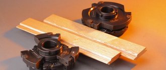
Which wheels to take?
The saw blade is the most important part of the circular saw, the working part for which it is made. The entire design of the machine is also tied to it, so we need to decide in advance which disks we will use in our work, and how to choose the right one in absentia (online) according to the designations on it or in the description..
Types and designation systems of saw blades
The most common 2 notation systems. According to the first (item A, position 1 in the figure), the following are sequentially designated:
- diameter of the disk at the tops of the teeth, mm;
- cutting width, mm;
- diameter of the installation (landing) hole, mm. Typical (default) tolerance +0.05 mm is not specified;
- atypical landing tolerance (possibly);
- number of teeth;
- the letter T or pictogram - the presence of carbide tipped on the teeth;
- rotation speed - operating (nominal) simply in numbers, the maximum permissible with the prefix max.
According to the second system, it is mandatory to indicate the standard size of the disk in numbers separated by hyphens: diameter at the bases of the teeth, their number, landing diameter (the default tolerance is the same). For example, 190-36-30 in item B, pos. 2 means a disk with a diameter of 190 mm (at the tops of the teeth there will be 200) with 36 teeth for a 30 mm fit. The rotation speed is indicated separately, but here it is the maximum by default; labor is 10% less. The remaining parameters are indicated either by symbols (item B, item 2) or textually. The minimum rotation speed, at which proper cutting quality is still ensured, for certified disks with stabilizing slots (items 1, 2, 4, 5) is 50% lower than the working one, and for solid disks it is 25% less.
There are quite high-quality “non-system” disks on sale (items 3-5). But in all cases, simply “for wood” (items 2-4) means commercial wood, plywood, chipboard, laminate and other fairly high-quality wood materials corresponding to the specifications. It is dangerous to saw unseasoned raw wood with such a blade - it can jam and fly apart. For sawing wild wood, special discs are produced with the designations Forest (forest, item 5), Wildwood (wild tree), Timber (wood), Log (log), etc. Discs with such designations are used in stationary pendulum saws, circular sawmills and other equipment for sawing raw wood.
Note : if you are going to saw metal with a circular saw, be careful - discs for steel and aluminum are not interchangeable. Universal discs for sawing any materials are also sold, but they work roughly. It is impossible to saw laminate, chipboard and other laminated materials with “station wagons” - the coating will peel off.
Finally, many saw blades go on sale without any markings or pos. 6 in Fig. In general, they cut, but you need to be careful with them: it is better not to give the linear speed of rotation of such a disk more than 40 m/s. To obtain the rotation speed from it (to calculate the gear), we measure the diameter of the disk at the bases of the teeth D (in mm), and calculate its operating rotation speed as 60(40,000/(3.1415xD)). For example, the operating speed of rotation of a “cloudy” disk of 200 mm will be 3815 rpm; It's better to take 3500.
Manual with gauge
A home craftsman rarely has to cut deeply and “long”, and a hand-held circular saw is a useful thing in itself. In addition, with a hand-held circular saw with a guide rail, you can cut wood both across and along the grain, and at any angle. And a cutting length of up to 1.5-2 m is quite enough for almost all finishing works and embodied creativity.
There are enough reisshins for manual circular saws on sale, and they are inexpensive, but there is no universal one. The principle of the construction of a branded rod is illustrated in the figure: the base plate (shoe) of the saw is made with a longitudinal groove, and the rod is stamped accordingly. comb (shown by the arrow in the figure).
Using a hand-held circular saw with a guide rail
It’s convenient to work with: you only need to press the tool from above, and it won’t go sideways or become skewed. And it’s also convenient during competition: we make our saws so that they don’t sit on the guides of our “partners.”
It’s inconvenient for craftsmen - you can’t find a cheaper tire. And a circular saw with a groove for the guide is disproportionately expensive compared to the same one, but with a smooth shoe. Amateurs do the opposite: a crossbar with a groove made of laminated plywood, and a pair of bosses are attached to the shoe (item 2b in the large figure at the beginning). But for this, firstly, you need a wood milling table, which you still need to make (not easy) or buy (expensive). Secondly, the already small cutting depth is reduced by 16-20 mm. Thirdly, if the tool is still under warranty, then drilling holes in the shoe will void the warranty. Fourthly, if the saw is rental, then nothing can be modified in it.
There is another way, but the tool will need to be held in 3 planes during operation: pressing, from moving to the side and from turning. In this case, the plywood base of the guide can be thinner, 6-8 mm. The actual crossbar will be a flat strip (or a piece of steel angle, etc.) attached to it, see next. rice.:
How to make your own guide for a manual circular saw
“Setting up” the device comes down to simply cutting off the excess from the base with a circular saw. This guide is attached to the board/sheet of material with clamps, just like the branded one. When working on a workbench, spacers with a thickness slightly larger than that of the material are placed under the base; depth of cut from this resp. decreases.
Adapter for electric motor shaft from a bolt
Many summer residents and owners of private houses were faced with the need to process and saw boards, plywood and other lumber.
For such work you will need a circular saw, which will not be difficult to do using available tools.
Such homemade equipment will not be inferior to purchased equipment in functionality and quality of execution, allowing you to save several tens of thousands of rubles on the purchase of ready-made units.
Description of equipment
DIY circular saws can be stationary or portable.
The design of the simplest circular saw will include a metal or wooden supporting frame, inside of which are mounted an electric motor, an electricity supply control unit, a table top and the working saw itself, which is mounted on the circular saw shaft or installed through gears and a trunnion mechanism. The saw is located in a slot in the tabletop, which makes it easy to cut lumber, performing high-quality wood processing.
The table top can be made from lumber or you can use ready-made metal blanks for this.
Smooth easel tables are made from wood; such a table top will need to be covered with a durable metal sheet .
Otherwise, without metal protection, the wood will begin to wear out quickly, and the equipment will last several years during active use, after which complex and expensive repairs will be required.
First of all, you need to decide on the main tasks of the sawing machine. If you need to cut boards or firewood for the winter, then a simple installation of a sturdy table with a slot for a disk will be sufficient.
Some models imply the presence of an additional shaft to which knives, a jointer and a plane are attached.
Such universal machines are equipped with powerful electric motors, which allows you to perform a wide range of wood processing work.
When manufacturing a multifunctional machine, it is necessary to be guided by high-quality diagrams and drawings that will allow you to create universal and reliable equipment.
If you need to perform various types of carpentry work, then set up a coordinate table with guides. The existing stops and guides can be fixed at different angles, which allows not only to ensure safe operation of the machine, but also to perform high-quality wood processing, easily changing blades to saws of different diameters.
Advantages of homemade equipment
Homemade circulars are very popular due to their ease of manufacture, durability and reliability. Today, many summer residents use homemade units rather than buying expensive equipment in specialized stores.
The main advantages of this technique include the following:
- The versatility of the tool.
- Ease of manufacture.
- Possibility of significant savings.
- Reliability and durability of equipment.
The designs of stationary and mobile circular saws available on the Internet and in thematic printed publications make it possible to produce equipment for processing both thin workpieces and thick lumber. You can choose the simplest options that do an excellent job of processing lining, thin slats and plywood.
Characteristics and power
The functionality of using the equipment will depend on the correct choice of parameters, including speed indicators and drive power.
The power rating is affected by the maximum permissible diameter of the toothed saw. It is believed that to process lumber with a thickness of about 10 millimeters, an electric motor with a power of 1 kW will be required.
Based on the thickness of the processed and sawn timber, you should select the power of the electric motor.
Transmission from the drive in a self-made circular machine is best done using a V-belt. This allows you to ensure the necessary safety of using the equipment. When foreign objects get under the saw, the V-belt drive will slip on the pulleys, which eliminates injuries and jamming of the working disk.
Making a circular saw
Before proceeding directly to the manufacture of a circular machine, it is necessary to think through its structure and design, and ideally, select a drawing diagram according to which all work will be carried out in the future.
When planning the manufacture of the frame, it is necessary to remember that such a design must be stable and reliable . For industrial powerful saws, the base is made of reinforced welded metal structure.
For household models, you can use wooden blocks with plywood for the frame or weld a base from a metal corner.
The choice of electric motor used will depend on what kind of work and what kind of wood is planned to be processed on the machine. The drive can operate from a single-phase electrical network, or powerful industrial motors are used that operate from a three-phase electrical network.
You can make a powerful and easy-to-use circular saw from a washing machine motor. This won't be too difficult. Such motors are compact in size, operate on a single-phase network with a voltage of 220 volts, are reliable and are capable of operating at high speeds.
How to make a circular, maintaining a balance between economy, functionality and safety
Let's look at the main components that make up a home circular saw. You can make them yourself, but only if you have certain skills and tools.
Stand for circular saw
The frame can be made from a metal angle (channel) purchased from scrap metal collectors. If you have the means, contact a metal warehouse. Legs can be made from old water pipes, connecting them with corners.
A good option for a homemade frame made of rolled metal
IMPORTANT! The use of bolted connections is prohibited, since vibration will cause the fastening to come loose.
Electric welding must be used. Be sure to reinforce the corner joints with a jib. The upper part of the frame (on which the table will rest) and the podium for the electric motor are made from a corner with a side of at least 50 mm.
If the machine is equipped with wheels for movement, they must have steel rims and have locks. The higher the weight of the frame, the more stable the machine will be, and the safer the work will be.
What to make a table for a circular saw from?
The working surface is made of steel, duralumin or silumin sheet. It is permissible to use textolite, plexiglass or moisture-resistant plywood. Galvanized sheet metal is placed on top of the plywood.
The main condition is that the material should not crack from vibrations , have a smooth surface and not allow deflections under a weight of at least 50 kg. If the tabletop cracks or warps, the circular disk will jam.
Universal homemade table for a circular saw and router. I recommend watching this video
This will lead to injury and damage to the workpiece. The use of popular materials OSB and chipboard is undesirable. These materials are unstable to vibrations and can collapse at the most crucial moment.
There are two options for making a working groove for a circular disk:
- You can cut a groove.
- or place two halves of the tabletop at a distance from each other.
Popular: Self-sharpening circular saws is a task that is quite feasible for a home craftsman.
The disk should protrude above the table by no more than 1/3 of its diameter.
For any work, from sawing wood to carpentry, a reliable side stop is needed. This can be a metal corner or a block of hard wood. To adjust the working gap, you can provide parallel grooves on the tabletop or simply attach the stop using clamps.
The side stop must be parallel to the plane of the disc. The slightest deviation will cause it to jam.
Which motor to choose for a circular saw?
It is impossible to install the electric motor “by eye”. It is necessary to calculate the power. For a disk with a diameter of 350 mm, a 1 kW motor is required; for a disk with a diameter of 170 mm, 500 W is enough.
A good option is a motor from an old washing machine.
Washing machine motor
It is designed for long-term operation with medium load. If you plan to work with a disc larger than 350 mm, you can use a power unit from used industrial ventilation.
Large electric motors are usually installed on dampers (shock absorbers), which prevent unnecessary vibrations.
Table for manual circular saw
There are many designs of homemade sawing tables for manual circular saws, but most of them are the fruits of creative research and/or self-expression. However, they are quite functional. However, the optimal options for those who do not need to make and show, but work on it, are visible quite clearly.
This is a folding cutting table for a hand-held circular saw (on the left in the figure). Table top – laminated plywood from 12 mm; drawers with a height of 400 mm - furniture laminated chipboard 16-24 mm. It is undesirable to make the drawers composite from boards; the required rigidity of the table will not be achieved. Tabletop overhangs – 30-60 mm.
Construction of a saw table for a hand-held circular saw
The design of the tabletop of the circular table is shown on the right in Fig. Through grooves for the exit of the saw blade (one groove is possible) are cut with a width of 6-10 mm. Special precision is not required, because the stop (see below) is set for cutting along the saw blade. The dimensions of the tabletop can be changed arbitrarily (up to approx. 900x1200 mm from 16 mm plywood). Fixation in working position (node C in the figure) - with M8 screws and wing nuts. The rotation unit (pos. B) is a piece of pipe (possibly plastic). Its fastening to the tabletop can be done with countersunk screws through through holes.
Instead of loops - L-shaped pieces of D8 rod; A slight play in the pipe does not affect the quality of sawing. Each “loop” is additionally bent in a vertical plane at an angle of 30-45 degrees. Threads are cut on the long “G” sticks, and they are secured in the frame with pairs of nuts and split washers. It is better to mark the mounting holes in the drawer in place by inserting the “loops” into the pipe and laying the tabletop on the base.
Emphasis
Make a massive sliding stop for the workpiece, as in pos. 3b in large fig. at the beginning, not necessarily. It is better to make it (the stop) from a piece of steel angle from 40x40, cutting off the vertical shelf as shown here in Fig. (back view).
The design of a sliding stop made of a steel angle for a homemade circular table
Such a stop is attached to the tabletop with clamps, and its parallelism to the saw blade must be verified in any case; This is done with a mechanic's square with millimeter divisions.
Tool holder
Fastening a manual circular saw in a saw table in clamps
The circular is attached to the underside of the tabletop with the disc facing up. If the tool is not under warranty and the loss of cutting depth is not significant, 4 D8 holes are drilled in the saw shoe, and it is secured with through screws with countersunk heads. It is highly advisable to lay 1-2 mm rubber between the shoe and the tabletop (for example, from a camera), the quality of the cut will noticeably improve due to the damping of tool vibrations. If the loss of cutting depth needs to be minimized, a through cutout is made in the tabletop for the tool shoe, the saw is attached to a steel sheet 3-6 mm thick, and it is attached to a rectangular hole on the front (working) surface of the tabletop (see figure on the left) . But you will have to select the hole using a hand-held wood router; a chisel will definitely not make it flush.
If the tool is under warranty or rental, loss of cutting depth is inevitable, because You cannot put holes in the saw shoe. For such a case, there is a known option for fastening the saw in clamps (see next figure). It’s not suitable for regular work in large volumes, but it can be done quickly and you’ll be able to cut smoothly in a day or two.
Attaching a hand-held circular saw to a saw table with minimal loss of cutting depth
Note: for information on options for self-manufacturing sawing tables based on hand-held circular saws, see the video; stationary to the workshop:
Video: converting an Interskol hand-held circular saw into a circular saw
desktop home:
Video: making a tabletop sawing machine
foldable in a suitcase for work on the road:
Video: portable compact sawing machine
Designs of homemade machines
There are three main elements at the heart of any circular, two of which cannot be made by yourself:
- engine.
- shaft, with jointing knives or the simplest, without them.
Third, the bed (table) is easy to make on your own.
You can make such a stand with your own hands without any problems.
Additional elements are also required:
- starter, switch for the electric motor;
- electrical wire;
- drive belt;
- pulleys on the shaft and motor.
For circular machines with an internal combustion engine (ICE), instead of a wire and a switch, a fuel tank is needed.
Main types of structures:
- The disk is mounted directly on the engine, without a belt or gear drive.
- The disk is mounted on a shaft with a belt drive.
- The shaft is the simplest, only for the disk.
- Shaft with jointing knives.
The first option is the simplest, but with a big drawback. The height of the engine “eats up” most of the working diameter of the disk. If the engine has a diameter of, for example, 200 mm, then a disk with a diameter of 200 mm will protrude above it by only 100 mm. Another part of this distance is reduced due to the motor mounts, connection box, and the thickness of the desktop.
As a result, only the outermost part of the disk diameter, where the greatest “lever” of resistance to engine rotation will actually work, will work. Even with a large blade, the cutting depth remains small, since the blade protrudes little.
If you install the motor with the blade on the side of the table, with the motor elevated relative to the table, the width of the cut will be limited. The wide piece will rest against the engine housing. It is impossible to extend the motor shaft with attachments, since the disk must be located as close as possible to the bearing. In another case, decentration of the shaft, beating and wobbling of the disk are possible.
The second option, the simplest shaft, also inevitably “eats” the working height of the disk, but much less. Only to the height of the bearing carriage from the center of the shaft. Therefore, when choosing a finished shaft, the height of the carriage matters. For powerful shafts this is 80-120 mm (40-60 mm from the center of the shaft). For thin shafts with small bearings 60-80 mm (30-40 mm).
The option with a shaft and belt allows you to select the number of revolutions of the saw blade due to the size of the pulleys on the motor and shaft. The belt can also act as mechanical engine protection. If it is not tightened, when the disk gets stuck in the workpiece, the belt slips along the pulleys, but the engine does not jam.
The option with jointing knives significantly expands the capabilities of the machine. The design can be more complex, with the front of the table being raised to adjust the planing depth.
The simplest option is also possible, without an adjustment platform. In this case, the planing depth is set by the position of the knives in the shaft itself. This option is suitable for rough processing. For example, on jointing knives with a planing depth of 3-5 mm, you can plan one surface lightly. Then, having one flat plane to move along the table, cut the workpiece on the remaining sides with a saw blade.
Stationary with jointing
It is better to immediately design a stationary circular saw with a jointing drum. Without it, most of the work on its production will simply lose meaning, except perhaps for the sake of the creation process itself.
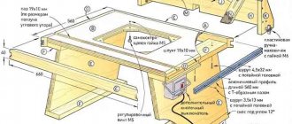
The structure of a stationary circular saw with a jointing drum is shown in the figure:
The device of a stationary circular saw with a jointing drum
When designing it, it is necessary to apply additional safety measures and ensure the quality of the machine. Firstly, during sawing, the jointing drum must be covered with a securely fastened protective cover on the pads to the jointing depth or slightly more, pos. And next. rice.:
How to adapt a jointing drum to a stationary circular saw
Loss of cutting depth will be approx. 6-8 mm (jointing depth up to 3-4 mm + 3-4 mm thickness of the lid. For jointing, a working pad of the same thickness (pos. B) is attached to the tabletop along its entire length behind the drum (along the workpiece). . overhang of the finished part behind the drum will lead to its planing onto a wedge; very flat, but due to the accumulation of errors during the construction or finishing work, it may turn out that all the processed material is damaged.
Note : by increasing the thickness of the working pad, you can adjust the jointing depth from maximum to 0.5 mm.
The motor matters
Secondly, the safety of using a homemade circular saw and the quality of sawing with it (especially finishing materials) is largely determined by the external characteristics (VnH) of the machine drive motor. ВнХ is the dependence of the torque on the shaft T on its rotation frequency N; the rotational speed (RPM) depends on the cutting resistance of the material being processed, and this, in turn, depends on the speed and feed force of the workpiece.
The VnH of a sequential excitation commutator motor (grinder, drill, hammer drill) is not monotonic (see figure).
External characteristics of a series-excited and asynchronous commutator electric motor with a squirrel-cage rotor
The maximum torque occurs at a certain rotation speed nр, slightly lower than the idle speed (without load) nхх. This is good: in the area of operating loads on the shaft ΔTр, the harder the material is, the stronger the motor turns the saw. Changing the feed force within these limits has virtually no effect on the quality of the cut, because the disk keeps the speed within the optimal range, and you can work at the highest performance.
The same thing, but without “adjusting” the saw to knots and other irregularities, is observed in a fairly wide range of overloads (ΔT region), i.e. High qualifications and a subtle tactile sense are not required from the operator - a beginner (not armless, of course) applied it once or twice, and that’s it, the work started. But, if you press hard, or something like a nail comes across, a dangerous property of the commutator motor appears in this case - a significant zero torque T0. An engine whose armature is forcibly braked will strive to turn at all costs: the workpiece can turn out and give you a kick in the teeth; the disk will fly apart.
Note : in manual circular machines, parallel-excited collector motors are used and/or with special armature winding circuits that reduce T0, but at the same time the “hump” of VnH is smoothed out. Therefore, in drills and grinders, where the “gnawing” ability of the tool with a small working stroke is important, T0 remains large. That is why it is impossible to put a saw blade larger than the standard one in the grinder - defects in work are inevitable, and the likelihood of injury increases sharply; This applies to abrasive discs to a lesser extent.
The VnH of an asynchronous electric motor with a squirrel-cage rotor is monotonous and quite rigid (in the same figure on the right). In the rotation speed range nmin – nmax that is optimal for a given disk, the feed force must be maintained very precisely, sensitively feeling the resistance of the material, i.e. Quite a high level of working skill is required. “Overfeeding” leads to a drop in both productivity and cut quality - a too slowly rotating disk tears the material. But if the saw suddenly jams, the motor will stop and begin to accelerate until the load is completely removed. If a 3-phase motor with a starting device from a single-phase network is used, then it will have to be turned off and restarted. When sawing long lengths, when the likelihood of awkwardness in work increases greatly, this quality of “asynchronous” VnH becomes valuable - a beginner/amateur can gradually learn to work without risking himself or spoiling a lot of material. Therefore, a homemade circular jointing machine should only be made with an asynchronous AC electric motor with a squirrel-cage rotor.
Motor mount
High-performance industrial circular saws, designed for long-term, round-shift operation, are equipped with large and heavy motors of 3-5 kW or more. Among other things, this reduces the sensitivity of the saw to material inhomogeneities and expands the range of permissible feed forces (see above), which, in turn, reduces the dependence of the quality of work on the qualifications and fatigue of workers. Another feature of circular saws compared to sawmills is that the belt drive from the motor to the disk turns out to be better than a chain drive, since you need to cut cleaner, but the material is of higher quality.
However, the belt tension weakens over time, so the engines of industrial circular saws are placed on supports that slide (and are fixed) in grooves (shown by arrows in position 1 of the figure).
Advantages of a pendulum motor suspension in a homemade circular saw over a sliding one
It is unrealistic to cut a long, even groove in metal without special equipment (a metal milling machine), but a 1-2 kW motor for a household circular is sufficient, and it can be placed on a pendulum suspension (item 2). Belt tension is thus ensured automatically without time-consuming adjustment work. There is more wear on the belt in a pendulum suspension, but you don’t work a full shift on your circular machine every day.
Note : assembly unit for pos. 1 pic. Above is the pendulum saw module of an industrial circular saw, which allows you to quickly install the output of the saw blade above the tabletop. But in the context of this section, this is not significant, and the output of the disk of a homemade circular saw can be changed not so quickly, but it is structurally and technically much simpler, see Fig.:
The mechanism for raising/lowering the saw blade of a homemade circular saw
The suspension hinge (shown by an arrow in position 2) can be quite rough (a steel pipe placed on a pin and filled with grease), but this does not noticeably affect the quality of the cut. You can do without a hinge on a steel sheet s(4...6) with screw support-clamps (shown by the arrow in position 2a). An additional advantage of the pendulum suspension of the motor is that the work table can be made tiltable, pos. 2b. When sawing a large amount of long timber (for example, for a construction site) by a sufficiently experienced worker, this significantly reduces his fatigue and speeds up the work.
Note: video material about building a circular saw with a jointing drum (sawing and jointing machine) on your own, see also the story:
Video: a simple homemade circular saw with a jointer
Rotation unit
The bearing assembly (rotation assembly) is the most complex and loaded part of a circular machine. We will try to make do with a minimum of expensive precision custom turning work.
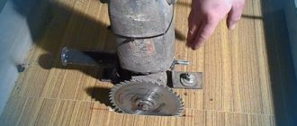
Drawings of a homemade bearing assembly of a traditional design are shown in Fig.
Drawings of a bearing assembly for a homemade circular saw
Critical dimensions are highlighted in color:
- At pos. 3 D32 – for the installation size of the saw blade (see above). Tolerance –0.05 mm.
- At pos. 4 D40 – for installation of bearings (see below). Tolerance +0.03 mm. Misalignment is no more than 0.01 mm. Finish sharpening in one setting on a high-precision machine.
- At pos. 6 D17 – for bearings. Tolerance –0.03 mm. Misalignment is no more than 0.01 mm. Finish sharpening in one setting on a high-precision machine.
- The pulley (item 7) is machined to size according to the gear ratio, based on the rotation speed of the existing engine, the diameter of the pulley on its shaft and the operating speed of rotation of the saw blade (see above).
Due to more stringent requirements for the cleanliness of the cut than for a sawmill, but the same as on it, or of a comparable length, conventional ball bearings, such as, for example, for a cutting machine, wear out quite quickly in a circular saw, and the saw begins to beat. Therefore, this design uses more durable bearings No. 60203; We will continue to focus on them.
How could it be simpler?
The described design of the bearing assembly is not without serious drawbacks:
- no jointing drum;
- turning the internal diameters clean in one setting is not a task for an amateur turner or even an entry-level specialist;
- from the heat when welding the bearing race 4 to the support plate 5, the race may move, and the bearings will not fit into the sockets, and it is possible to grind them cleanly in the assembly only on a rotary or shaping machine.
Unreliable design of the housing and bearing assembly of a homemade circular saw
With a jointing drum, it looks like it can be solved: cut the frame with the slab in half, and that’s it. But adjusting the machine to verticality and eliminating the misalignment of the saw blade outside of production conditions will cost painful work with no guarantee of success. Or you will have to machine the mounting pin with high precision (for one-time use). But then, so that the setting does not soon float away, you need a strong, rigid body of the machine. Like welded UBDS-1 or UBDN-1. A homemade analogue with threaded connections (see figure on the right) will quickly become loose, and after 2-3 readjustments the bearings will also break.
Unconventional approach
What if we completely abandon the holder with the base plate? Then only the shaft will need to be sharpened with high precision. How to attach it? In wood to wood, this will further simplify and reduce the cost of the machine. Wood is an archaic material, expensive and poorly technological in mass production, but not bad for piece work. In the old days, wooden sailing battleships served for 120-150 years, with periodic upgrades. And modern 40-year-old warships are subject to renewal only if there is no ready-made full replacement.
The method of attaching the bearing assembly of a homemade circular saw in wooden cages to a plywood tabletop is shown in the figure:
Fastening the rotation unit of a homemade circular saw in wooden cages
The frames require dense, fine-grained, fairly elastic hardwood. The best is maple; further – walnut, hornbeam, oak. In this case, a durable rigid body of the machine is also not needed; a simple “bedside table”, like for a table for a manual circular saw, is enough. Modern achievements include furniture screws - confirmed ones; in fine-grained wood they fit tightly and do not come loose from vibrations. The “trick” of the design is that during the adjustment process (see below), the bearings are pressed into the wood and thereby securely fixed.
Assembly of the entire assembly is combined with adjustment:
- A groove for the saw blade is pre-cut in the tabletop and holes are drilled for the heads of the D6 confirms.
- Pioneer (installation) holes for confirmations D4.8x60 are also pre-drilled in the clip blank.
- Empty clips are “baited” so far only with the top confirmations.
- A shaft with bearings is inserted into the cages.
- A saw blade is mounted on the shaft.
- The upper confirms are tightened so that the bearings fit into the cages without play, but not tightly.
- The disk is wedged in the groove symmetrically with 4 pairs of wedges: 2 pairs on top closer to the center, 2 pairs on the bottom closer to the edge.
- By tapping the wedges, align the disc along the slot and vertically.
- The upper confirmations are tightened until the heads are recessed flush with the table top.
- The confirmations are tightened alternately on both clips in 3-4 steps using an “envelope”, i.e. with a diagonal transition.
- Leave the assembly to “settle” overnight or, better, for 2-3 days, so that the bearings are pressed into the wood.
- Take out the wedges and check to see if the disc has moved. If the confirmations were tightened carefully and correctly according to the scheme, it will not work.
- They place and tighten, also with an “envelope,” the lower confirmations.
- Let the tabletop with the bearing assembly “settle” one more time.
- Check the disk installation again. It didn’t lead, did you pull the lower ones correctly? The unit is ready for further assembly and operation.
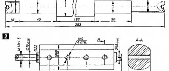
Shaft drawings for this design are shown in Fig.:
Shaft drawings for a circular saw with a jointing drum
The blank is round timber St45 D60. The finished shaft assembly with jointing knives must (!) be balanced in the centers. During balancing, the material can be selected both from the “raw” surface of the D60 and from the areas under the knives.
Algorithm for assembling a homemade circular saw
The assembly of a woodworking machine according to the drawing given earlier is carried out in the following sequence:
- a rectangular frame is made from the corners;
- four legs are welded to it at the corners of the required height;
- at a height of about 200 mm from their lower edge, they make a binding from the corners;
- a shaft is mounted on the upper frame;
- fix the driven pulley on one side and the disk on the other;
- a table with a lifting mechanism is made and attached to the frame;
- on the lower frame they make a platform from corners or sheet metal for the electric motor;
- the drive pulley is fixed on the motor shaft;
- put the belt on the pulleys;
- On and off buttons and an electrical panel are mounted on the side panel of the unit;
- using wires of a suitable cross-section, connect the elements of the electrical circuit of the equipment (motor, buttons, protection);
- supply power to the machine from a stationary network.
The final stage is to check the functionality of the assembled equipment. First, you should make sure that all moving parts rotate freely: to do this, simply twist the drive pulley by hand. After which you can start the unit in test mode. If strong vibration is detected, you will need to check the reliability of the bolted connections and fixation of the disk.
You can make a circular saw with a table consisting of two halves or a solid one. In the latter case, you will need to cut a rectangular slot in it for the disk. The design of the machine with a table consisting of two halves is shown in the video below. This video also demonstrates the design of the lifting mechanism for these parts.
Important! To prevent the possibility of the saw jamming due to the connection of fragments of the workpiece being cut, it is recommended to install a riving knife. It should be located at a distance of approximately 3 mm behind the disc.
And one more device
But what if you need to cut the workpiece across or at an angle? Making a cutting machine? Perhaps with your own hands, but for thin workpieces (boards, parquet, laminate, door frames) it is not necessary.
For such purposes, there are transverse/angular carriages for circular saws.
Design and drawings of transverse/angular carriages for a circular saw
If there is a milling table or access to it, then select a longitudinal groove in the tabletop (removed from the machine) and make an angular stop for it (top left in the figure); The arrow shows the direction of feeding, and during it the workpiece is pressed against the stop. If not, you can make a transverse carriage (bottom left and right, drawings); perhaps with a focus on the most sought after fixed angle of 45 degrees. For cross-cutting, the board is laid along the carriage; for cutting at 45 degrees - with a skew. The carriage is moved so that the saw blade passes through the slot in it, that's all. It’s not very good that a lot of cutting depth is lost, but when the disc reaches 50 mm, boards up to 20-25 mm thick can be sawed. Additionally, a video on how to make a transverse carriage for a circular saw:
Pros and cons of a homemade sawing machine
Advantages
The ability to make a unique machine of the required power and size to suit your needs.
The cost of assembly can be minimal if all or part of the original components are available.
In any case, homemade frames, as a rule, are durable and massive in comparison with modern flimsy Chinese machines from stores.
A powerful homemade circular saw is capable of performing rough and heavy work that only industrial equipment can do, and which household machines cannot withstand. Industrial circulars cost tens and even hundreds of thousands of rubles. The homemade option is many times cheaper.
Flaws
Modern factory-made stationary circulars for the home, despite their fragility and relatively high price, have a number of advantages. As a rule, they are all equipped with various degrees of adjustment or some of them.
- planing depth;
- tilting the disk at an angle;
- speed adjustment;
- gear transmission with a significant increase in saw blade speed;
- well-thought-out protection systems.
Performing all these options entirely on homemade machines is difficult, difficult and expensive. Therefore, for small precision carpentry work and furniture production, factory machines with a full range of functions are better suited. The homemade version is well suited for rough work with large-sized wood and primary processing.