A circular saw is a device that is used mainly in industry, but you can find people using it in private home settings. Some people try to make it themselves. The most important part here is the shaft. Most often, the shaft for the circular is made to order. To do this, you need to contact only a highly qualified turner. Fortunately, it’s not difficult to find something like this today. However, such work will be quite expensive. There are alternative methods to solve this problem. The easiest way is to create a shaft for a circular saw with your own hands. Of course, this requires a lathe.
Circular shaft drawing.
It is even possible that it will be numerically controlled. You will have to acquire some additional tools. You can't do without materials here.
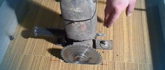
Circular saw shaft
Shaft for a circular saw and bearing assembly
Let's look at the picture, which shows a sectional view of the shaft assembly
• shaft (1) • bearing housing (2) • bearings (3) • internal saw blade clamping sleeve (4) • external saw blade clamping sleeve (5) • clamping nut (6) • driven shaft pulley (7) • clamping nut, lock washer, key (8)
Sharpened from steel 45. The manufacture of the shaft can only be entrusted to highly qualified specialists, where a prerequisite is strict compliance with the technical requirements for the seating surfaces of shafts and housings in accordance with GOST 3325-85. On the saw blade mounting side, the following are mounted on the same diameter: a bearing; clamping inner sleeve; saw blade; clamping outer sleeve, so take this into account when you add tolerances and fits to the working drawings.
It is sharpened from steel 20. M6 threads are cut into the four mounting holes. Before pressing the bearings, fill the housing with Li-tol-24 lubricant.
1204 ball radial double-row spherical GOST 28428-90. They have two rows of balls. The inner surface has a curved shape. Covers can be provided in the bearing housing to protect them from dust and wood chips. But this solution, in general, will significantly complicate the design and increase its overall dimensions, therefore, we will not use it.
INNER CLAMPING BUSH
M16 round spline nut GOST 11871-88, clamps the saw blade.
We will make it from aluminum alloy according to the general technical specifications GOST 20889-88.
The M16 round spline nut in accordance with GOST 11871-88 clamps the driven pulley.
Multi-claw (version 2) GOST 11872-89, serves to fix the nut relative to the shaft and does not allow it to unscrew during rotation.
Keyed connection with parallel keys, tolerances and fits GOST 23360-78. We select the length of the key from the size range - 22 (mm)
Well, and most importantly, in order for the assembled unit (shaft for a circular saw) to work without the slightest runout, it needs to be balanced in the factory using special equipment.
In the next article we will look at the construction of a circular saw bed.
Source
Design - main components, their purpose
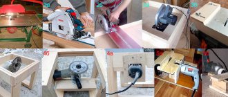
A do-it-yourself stationary circular saw is created with advancement in several possible directions:
- adapting existing hand tools using the motor and circular saw for new capabilities;
- improvement of industrial products to expand functionality;
- assembly of individual parts, manufactured mainly in-house.
A stationary circular machine includes several main components: a table, a shaft, a motor and some others, the characteristics of which are not so important.
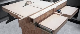
Making a workbench with a built-in saw cheap and cheerful
The table is used for fastening woodworking mechanisms. It can be assembled entirely from metal, which is preferable, especially for machines with a high-power engine. Wood also makes good circular tables. But it is necessary to take into account that the tabletop should be covered with a sheet of metal, otherwise the wood will soon wear out. Tables must be very rigid and stable, capable of withstanding considerable load during work. The surface is made perfectly flat; protective shields must be installed above the rotating parts.
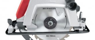
For a homemade circular machine, a washing machine motor is quite suitable. Portable tools are less suitable: their commutator motors are designed only for short-term work. They have very high speeds, low efficiency, and are afraid of clogging. You can use a three-phase electric motor, but if the household does not have 380 V, you will need to purchase capacitors to make it work on 220 V.
The most critical component is the shaft. Use a ready-made one, if available, or machine it from round metal. The work on the lathe is performed in one setup, then the assembly with the working parts is checked for centering. Even minimal runout is unacceptable, otherwise during work it will become stronger, at which it is unacceptable to work. Seats are provided on the shaft: for a circular saw and for pulleys on the other side. You can also make grooves for planing knives.
What is it, types and functions
Such a device is necessarily included in the design of format-cutting circular saws. This is a movable part of the work table, which, together with the workpiece fixed in it, moves along strict guides of the relative saw blade. Thanks to this, the cut line is perfectly straight.
The cutting itself is easier, since the workpiece moves strictly, does not wobble, and there is less friction between the material and the disk. The workpiece itself does not need to be moved along the work table by hand or pusher. It is easier to move the carriage with the workpiece, especially if it runs on bearings.
Dozens of different carriage designs are used. Let's look at the most popular of them.
Factory designed
They are installed on stationary general-purpose circular saws and on sizing saws. In the latter case - for cutting large sheets of chipboard, MDF, laminated material, plywood, fiberboard, etc. Therefore, they have a large support area for sheets and a long stroke length, sufficient for cutting long sheets.
On general-purpose circular saws, the slides are much smaller. Designed for precise cutting of small and medium-sized workpieces made of sheet material and wood (boards, beams, slabs) and other materials.
An example of such a circular in the photo:
Making at home
The main thing is to accurately maintain the geometry. The basis could be:
- channel;
- pipe with a rectangular cross-section;
- corner;
- laminate.
A serious disadvantage of wooden and pressed tires is their sensitivity to moisture.
Option 1. Laminate tire.
- Using a ruler, cut two pieces of material of the same length.
- We mill one edge at a time.
- We attach it to the base (also made of laminate) with self-tapping screws.
- We check the width of the groove using an A4 sheet of paper with a thickness of about 0.11 mm: the paper is inserted into the device and screwed.
- The tire is fixed to the sole of the circular saw with a mount for a side stop. You can drill a hole in the housing if the warranty period has expired.
- The bar extends as far as possible in front of the hand-held circular saw. The toe of the sole should extend a few centimeters onto the guide. Using a laminate sawing disc, we saw off the edges of the guides so that they align with the markings.
This will absorb the depth of the cut (approximately 1.5 cm), but such a device is convenient and easy to manufacture.
Option 2. The basis is the building rule. A model with handles that move along a groove is suitable.
- The handles are removed, and softly fixed clamps with spring handles are selected instead. Models with a removable top are suitable. Having removed the upper part, the clamp is fixed to the rule using an adapter.
- Adapters are made from polypropylene on a milling machine. The result should be parts that, in cross-section, resemble the letter “T”. They are inserted tightly into the groove for the handles.
- Holes are made in the “leg” of the adapters and screwed onto the screws with clamps.
- The tire is laid on the sheet with the groove down and pressed firmly from below with clamps. There are no parts on top that slow down the operation of the circular saw. The only limitation in work is the length of the rule.
Option 3. To obtain an accurate cut, the edge of the tool base adjacent to the guide must be perfectly smooth. Professional tools with cast soles are distinguished by this, but inexpensive stamped bases do not have this property. Therefore, we offer the rail option. The tool moves along it without resting against the guide rail. At the same time, the force required to push the saw is significantly reduced. The rail can be made of aluminum U-shaped profile. You need two segments with different sections. The smaller profile is inserted into the larger profile without any gap, but free movement must be ensured.
Homemade options
The simplest version does not have bearings, a mounting frame, profile guides and platforms that move along them. A movable table made of sheet material moves along a fixed work table. Left-right movement is prevented by limiters installed on both sides.
A more complex option is that the slide platform moves on bearings that run along grooves in the limiter. The disadvantage of this option is that when the guides are located on top of a fixed work table, the bearings significantly raise the working platform of the slide, which reduces the working diameter of the saw blade (depth of cut).
Other “semi-homemade” options with ready-made linear guides described above. Their moving platform has special sliding bearings built into them.
We also recommend reading an interesting article about guides for circular saws, in which we discussed in detail what they are and how to make them yourself.
Manufacturing process
After all the tools and materials have been purchased, you can proceed to the next steps. You can make a high-quality circular table with your own hands if you correctly carry out the work according to the drawings and, in fact, the construction of the structure.
The manufactured table will be level and convenient for work only if the correct calculations are made. If you are not confident in your abilities when preparing drawings, you should seek help from a specialist.
Create a drawing
This is the first and very important stage of work, which is also called preparatory. Correct drawings for circular installation will avoid many problems in subsequent stages. You need to decide what the exact dimensions of the table will be and draw them on paper or on a computer.
Important points that must be taken into account when drawing:
- The dimensions of the hole in the working surface must be selected for the specific saw model. It is impossible to make a design that will fit all saws at once. The frame must withstand all loads without problems, so only precise selection of dimensions is necessary.
- The table must be centered. Overweighting one part will lead to difficulties in working. But the dimensions of the table should be selected based on the dimensions of the room in which it will be installed and the personal wishes of the master.
- Multifunctional table. If the table is planned to be made not only as a work surface, but also as a place to store tools and materials, then the dimensions of the table top are made with a margin. Experts recommend drawing a tabletop larger than one m² at the drawing stage.
How to make a movable carriage for a circular saw with your own hands
The simplest version of the sled is shown in the following video:
Step-by-step manufacturing instructions
The production of such simple options is carried out according to the following sequence.
Size calculation
They must match the size of the work table, taking into account the size of the workpieces that will be sawed. Small workpieces require a small area, and vice versa. In the video shown, the sled is much wider than the desktop; additional supports are used.
Material selection
We use material that is on hand or on sale at an affordable price.
- Layout of sheet for desktop.
- Sawing material onto a moving table with a jigsaw, hand or electric saw, angle grinder, etc.
- Measuring guide bars (angles, profiles) for longitudinal and rear transverse stops.
- Sawing guides to length.
- Assembly. The main thing is that the guides on both sides are strictly parallel to the disk. To do this, the following order is maintained: One guide is screwed on, the slide is put in place. The second guide is screwed to the actual location of the slider. Then the work table of the sled is cut for the disc using the wood saw blade itself. In this case, the slide is simply moved towards the working disk. If the table is made of metal, it is cut with a metal disc according to the markings.
- Installing the rear thrust bar.
In the version shown in the video, a side stop is used as a cut width regulator - a simple U-shaped metal profile on a clamp.
The main disadvantage of this design is that at the slightest misalignment of the guides, the table will jam. Distortions during movement are quite possible, since the guides move without bearings.
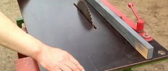
In the photo, the side guides are made in a different way.
Here they are not attached to the sides of the fixed table, but are located below. Sliders are attached to the bottom of the slide; there are grooves for the sliders on the fixed work table.
This option is less prone to warping and jamming.
Assembling the frame with legs
The base or frame of the table is assembled from a set of transverse and longitudinal wooden beams, which are attached to the bottom of its lid, increasing the rigidity of the entire structure as a whole. For this, four bars with a cross-section of 50x50 mm, placed at a distance of about 7-9 cm from the edge of the table, are sufficient. They are fixed on the bottom of the lid with self-tapping screws of suitable size in increments of approximately 23-25 cm. On its front side, the fastening elements are recessed into the material, completely hiding their hats. The frame can be made stronger by pre-treating the mating surface of the bars with a layer of wood glue, carried out immediately before attaching them. After joining the glue-coated workpieces, the latter are securely fixed with clamps, which are removed immediately after the adhesive has dried. The legs of the structure can be made from bars of the same cross-section as the blanks for the frame (50x50 mm).
The structure of the table must be strong and rigid
The shape of the legs is chosen so that they provide maximum support area for the frame part of the base and have a shape that tapers towards the flooring. On one of these legs, controls for turning the circular saw on and off are subsequently placed, duplicating the buttons located on its body.
You will be able to further increase the rigidity and stability of the entire structure with the help of a set of steel angles mounted in the area of its butt joints. To secure them, it is recommended to use standard bolts with washers, which should preferably be installed with their heads facing outward.
Nuances of work and safety precautions
Sleds are used to solve special problems. For example, for precise cutting of sheets, cutting many identical small workpieces to one size using a width stop, cutting at an angle. For the latter, the workpiece itself is placed at the desired angle on the movable table.
Processing of long workpieces is limited by the table stroke length. It will not be possible to cut a wane from an unedged board with a length of, for example, 6 m using such a device.
Safety precautions when working with a sled are the same as when working with a regular circular saw.
- the hand should not come close to the working saw blade;
- the workpiece must not be clamped;
- you cannot work tired, with reduced reaction;
- You should also remember about electrical safety. Exposed contacts and wires, unsuitable cables are not allowed.
In general, working with a carriage is safer, since the hand pushes the slide further from the saw blade than the workpiece on a simple circular saw.
What types of equipment are there?
Currently, there are several main options for machines on the equipment market that use spindle shafts:
- CNC machines are high-tech mechanisms with a computerized processor, suitable for processing both metals and wood, as well as some types of plastics. Allows you to perform work via a computer - the program contains the progress of work, types of processing, the operator can only place the workpiece and wait for the end of the process.
- Horizontal woodworking machines have a wide working surface and perform work only in a horizontal position of the workpiece.
- Vertical machine - the working unit is located vertically, which allows you to perform work in an up-down plane, which greatly simplifies the processing of some elements.
- A hand router is, of course, not a machine, but if you attach it to a desktop, you get an excellent portable device. In some cases, a copier can be made from a cutter to produce products according to a given sample.
Important!
Tabletop options are most often used by carpenters at home; machines of this type are good options for reasonable money. It is also worth remembering that each cutter has its own configuration and you will need several options to work (they are not sold with the machine).
Pros and cons of homemade products
The advantages are that you can do exactly what a particular master needs for relatively little money or even for free.
The downside is that the simplest homemade options cannot provide the ease and precision of movement that factory products with linear guides on plain bearings have.
It turns out that the carriage is a useful device, especially in a carpentry workshop, when high precision is required when sawing materials and, moreover, it can be made with your own hands and inexpensively. Remember, the strength, durability and performance quality of a homemade circular saw carriage depends on the quality of the build and the materials chosen.
Source
Profile bending without turning: price, parts, tools
Having decided to make a profile bending machine with his own hands, the master asks himself the following questions:
- Will a lathe be required?
- How much will a homemade product cost?
- Isn't it cheaper to buy a profile bender in a store?
To answer them, we’ll immediately show what portal participant Pin008 did.
And this is an example of work performed by a profile bender.
And this is a video showing the operation of this homemade pipe bender for a profile pipe.
If you are interested in a homemade pipe bending machine Pin008, then to make it you will need:
- bearing unit UCP 204 – 4 pcs.;
- straight channel 8 (shelf base height 8 cm, shelf width 4 cm) – 2 m;
- diamond jack from a passenger car;
- bearing 156704 – 3 pcs.;
- threaded rod M20;
- M20 nuts;
- washers for M20 stud;
- bicycle sprockets - 2 pcs.;
- bicycle chain.
- Bulgarian;
- powerful drill;
- welding inverter.
Next, we will tell you how to assemble a homemade profile bender from these parts.